

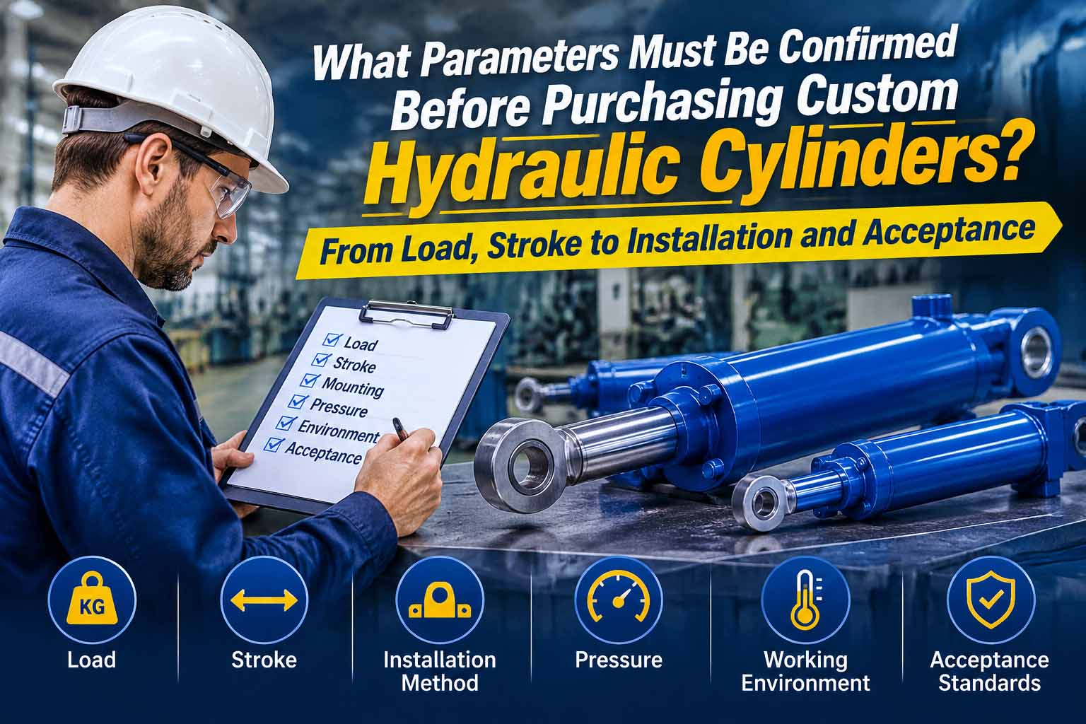
A request such as “How many tonnes can it push, and what is the stroke?” gives a hydraulic cylinder manufacturer a starting point, but often leaves too much information missing for a reliable quotation. Even bore diameter, piston rod diameter and stroke describe only the cylinder’s basic geometry.
Those dimensions do not establish whether a custom hydraulic cylinder can deliver the required force, follow the intended motion, fit the machine, keep its rod stable or use seals suited to the environment. Nor do they define how the finished cylinder will be accepted.
Start with the machine’s task and load, then organize the requirements into the following eight groups. This approach helps purchasing, mechanical engineering, hydraulic engineering and quality personnel agree on the technical conditions before placing an order.
1. Define the Machine’s Task and Actual Cylinder Load
First explain what the cylinder must do: where it sits in the machine, which component it pushes or pulls, the direction of movement, the start and end positions, and the time available. State whether it must hold a load after stopping and what movement, if any, is permissible after pressure loss.
List loads by operating stage: extension, retraction, starting, steady motion, deceleration, stationary holding and abnormal conditions. If the mechanism changes angle, identify the position that produces the highest cylinder load.
For example, a machine mass of 5 t is not the cylinder’s axial load. Actual cylinder force also depends on the force application point, lever ratio, mounting angle, guide friction, number of cylinders sharing the load, acceleration and external impacts. Pushing and pulling can involve entirely different conditions.
Include at least:
- A motion sketch showing the cylinder’s position in the mechanism.
- Working loads during extension, retraction and holding, including their directions.
- Load variation with position or time.
- Impact, jamming, eccentric loading and other external forces.
- Whether lifting, fall prevention or personnel safety is involved.
- The intended failure state and protective measures at machine level.
If information is unavailable, mark it “to be confirmed by the mechanical/safety engineer.” Neither the purchaser nor the supplier should silently replace it with an assumed value.
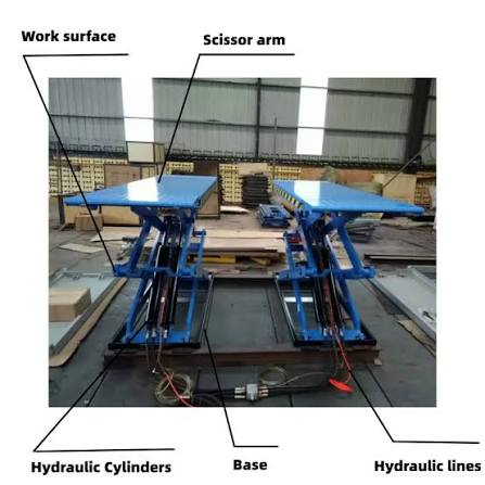
2. Specify Pressure and Force by Direction and Operating Condition
The basic theoretical relationship is P = F / S, where P is pressure, F is force and S is effective area. Extension generally uses the full piston area; retraction uses the annular area after subtracting the piston rod area. Speed depends on flow and effective area.
Manufacturers’ sizing information likewise relates bore size to required force and working pressure, and explains motion speed through flow and area. However, writing only “pressure: 16 MPa” is insufficient for a purchasing specification.
Distinguish four pressure conditions:
- Normal working pressure: pressure expected during the specified machine operation.
- Maximum allowable working pressure: the upper pressure the cylinder may withstand continuously or repeatedly under the specified conditions.
- Transient or peak pressure: momentary pressure caused by switching, emergency stopping, impact loads or control response.
- Acceptance test pressure: pressure specified for the agreed tests, to be defined when ordering.
Record working, peak and test pressures separately in the technical agreement, with relevant durations and operating conditions. Keep unconfirmed values open. The system relief valve setting must not automatically become the complete boundary for cylinder design and acceptance.
3. Confirm Stroke, Mounting Length and Installation Envelope
Stroke defines how far the piston rod travels. It does not establish the retracted mounting length or whether the extended cylinder will collide with another component.
Check the following on the same design drawing:
- Effective working stroke and any adjustment allowance.
- Mounting distance at full retraction.
- Mounting center distance or overall length at full extension.
- Connections at both ends, pin bores, flange holes and locating datums.
- Space occupied by the barrel, ports, valve block, sensors and fittings.
- The swept envelope during articulation, plus hose and cable clearances.
- Critical dimensional tolerances, mounting errors and site measurement datums.
When replacing an existing cylinder, measuring a removed unit is not enough. Confirm whether it is fully retracted or at an intermediate position, whether pins or spherical joints are worn, and whether the machine has been modified. Define the viewing direction used to specify port orientation.
Photographs help explain the application but cannot replace drawings with dimensions, directions and datums. For a compact installation, mark forbidden intrusion zones on the approved drawing. Two cylinders with the same stroke may have different end caps, eyes, valve blocks or fittings and therefore different installation compatibility.
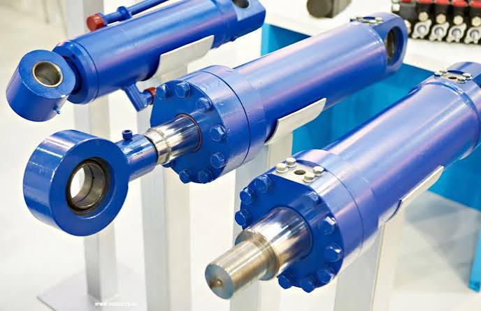
4. Define Extension Speed, Retraction Speed and Duty Cycle
“Make it move faster” is not a usable sizing requirement. Specify target extension and retraction speeds separately, or give the permitted travel time between defined positions. Where speed changes during the stroke, provide a motion–time or position–speed profile.
Speed depends on flow entering the relevant chamber and its effective area. Changing cylinder size therefore changes travel time if pump flow stays constant. Increasing speed also affects required flow, line pressure losses, port sizing and the control method.
Describe the complete duty cycle:
- Time spent extending, dwelling, retracting and waiting.
- Cycles per minute or hour, and operating time per shift.
- Continuous reciprocation or occasional movement after a long holding period.
- Whether several cylinders operate simultaneously and how flow is shared.
- Whether the load appears only near the end of travel, and whether deceleration or cushioning is needed.
- Permitted impact, vibration and noise, plus position repeatability requirements.
The duty cycle affects temperature rise, seal friction, guide wear and system power. End cushioning needs more detail than “included” or “not included”: specify the direction, deceleration start position, load and speed conditions, adjustability, and whether the machine controls already provide deceleration.
5. Check Mounting, Alignment and Piston Rod Stability
Mounting determines the motion the cylinder is allowed to make within the mechanism. A mechanism following an arc generally needs an articulated connection; linear movement can use an appropriate fixed mounting. Rod selection must also account for stroke and buckling risk. Bosch Rexroth’s configuration resources likewise link mounting position with buckling-length assessment.
Specify:
- Front and rear mounting types: flange, foot, eye, clevis, trunnion, spherical joint or another arrangement.
- Pin axis orientation, articulation plane and permitted angular travel.
- Trunnion position and orientation relative to the cylinder body.
- Dimensions, tolerances and lubrication of mounting faces, pin bores and supports.
- Whether the external mechanism provides reliable linear guidance.
- Possible misalignment, structural deflection and sources of side load.
- Maximum length under compression, end restraints and dynamic compressive loads.
A hydraulic cylinder is intended to transmit axial force; it should not serve as the machine’s guide. Significant side loading adds stress to the rod, guide bush, seals and mounting supports. Appropriate solutions may include changing the mechanism, adding external guidance, modifying mounting freedom or developing a dedicated design. Increasing rod diameter alone does not resolve the underlying issue.
A long-stroke rod under compression also requires a buckling check. Rod diameter alone cannot establish stability: extended length, mounting arrangement, end restraints, material, initial eccentricity, dynamic loads and safety requirements all belong in the assessment.
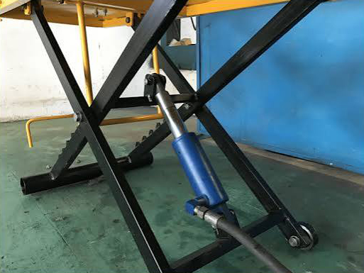
6. Match Seals and Materials to Fluid, Temperature and Environment
“Standard hydraulic oil, indoor use” can still leave essential information missing. Specify the fluid name or specification, viscosity range, minimum and maximum operating temperatures, starting temperature, contamination control requirements, and possible ingress of water or cleaning fluid.
For water-glycol, biodegradable, fire-resistant or other special fluids, confirm material compatibility before selection.
Describe external exposure to dust, sand, moisture, salt spray, chemicals, welding spatter, radiant heat, freezing conditions and outdoor ultraviolet light. Include food-related or cleanliness requirements and possible rod damage from stones, workpieces or tools.
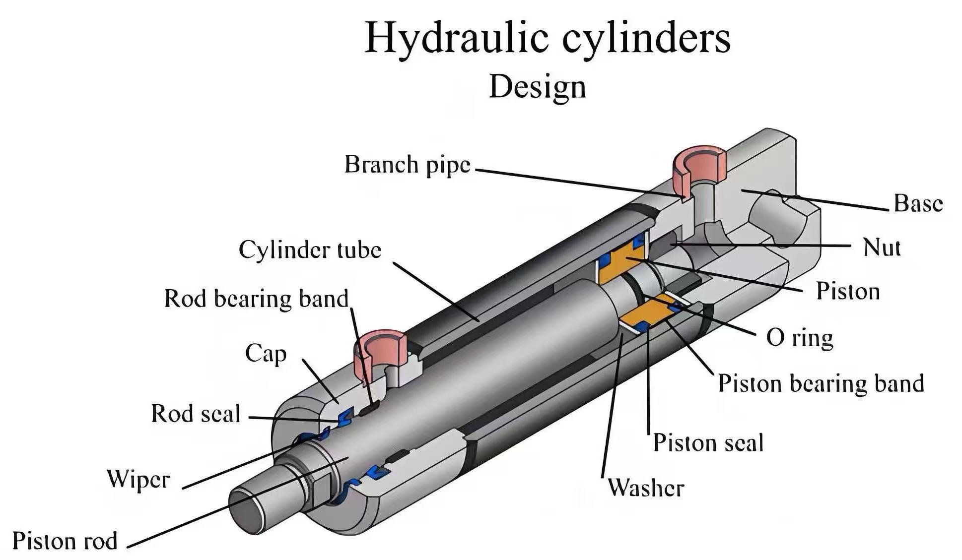
Each sealing and guiding component has a different role:
- The rod seal controls external leakage along the piston rod.
- The piston seal controls internal leakage between the two chambers.
- Guide elements carry transverse loads and prevent metal-to-metal contact.
- The wiper limits the entry of external contaminants with the moving rod.
Pressure, temperature, speed, fluid and side loading often act together. Individual maximum ratings cannot simply be combined. Provide complete operating conditions and expectations instead of selecting a seal material before the application is understood.
For the cylinder and machine system’s pressure-containing boundaries, installation, commissioning and maintenance, consider GB/T 3766—2015, covering general rules and safety requirements for hydraulic systems and components. Engineering personnel should check its applicability to the project.
7. Specify Ports, Cushioning, Sensors and Accessories
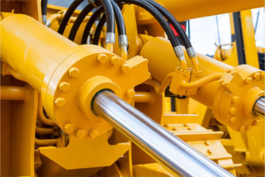
Identical interface names do not guarantee interchangeability. For every port, state the connection standard, size, sealing method, thread or flange depth, position relative to a datum, orientation, and space for installing and servicing fittings and hoses.
Also confirm:
- Which motion direction corresponds to ports A and B.
- Whether separate bleed, drain or pressure measurement ports are needed.
- Integrated valve blocks, check valves, counterbalance/load-holding functions or throttling elements.
- The cushioned end or ends, adjustability and safe access to adjustment points.
- Position detection by magnetic switch, proximity switch, linear displacement sensor or external encoder.
- Sensor measuring range, output signal, power supply, connector, protection rating and cable exit direction.
- Rod-end threads, clevises, spherical joints or anti-rotation requirements.
- Surface treatment, color, corrosion protection, transport restraints and port plugs.
For an integrated valve block, provide the hydraulic schematic, the limits of each valve’s function, responsibility for settings and maintenance clearances.
A cylinder-mounted valve does not by itself establish a load-holding or fall-prevention safety function. Complete a machine-level risk assessment and define the required state following hose failure, power loss and control failure.
8. Agree on Acceptance Tests and Delivery Documents Before Ordering
Acceptance needs measurable criteria in the technical agreement, rather than a visual impression of quality. Relevant references include GB/T 15622—2023, Hydraulic Cylinders—Test Methods, and ISO 10100:2020. Quality and engineering personnel should confirm the applicable scope of these references.
An executable acceptance matrix should define:
- The approved drawing revision, technical agreement and applicable standards.
- Dimensions, mounting interfaces, port orientations and accessories to inspect.
- Required function, stroke, pressure resistance, external leakage, internal leakage and cushioning checks.
- Test fluid, temperature, pressure, flow, cycles and holding conditions for each test.
- Measurement locations, instrument capability, data records and acceptance criteria.
- Approval procedures for nonconformities, rework, retesting and acceptance by concession.
- Required traceability for materials, welding, heat treatment, coatings, cleanliness and critical components.
- Language and format of factory test reports, certificates of conformity, final drawings, spare-parts lists and maintenance information.
Control drawing status explicitly: inquiry drawings, quotation drawings, approved manufacturing drawings and final delivery drawings must be identifiable. Obtain written agreement before manufacturing for any deviation affecting interfaces, pressure-containing boundaries, materials, seals, sensors or testing.
Before installation, testing or leak inspection, isolate energy sources, support any load that could move and verify that residual pressure has been released. A pressurized cylinder presents a serious hazard. Never check leaks by hand, tighten fittings under pressure or dismantle a cylinder whose condition is unknown.
A One-Page Specification Checklist for Your Cylinder Inquiry
Submit a structured specification rather than scattered numbers in chat messages. For each group below, record confirmed/to be confirmed, the responsible person and the reference revision.
| Parameter group | Minimum information to record |
|---|---|
| Task and load | Motion sketch; extension, retraction and holding loads; maximum-load position; dynamic and abnormal conditions; failure state |
| Pressure and force | Working pressure in both chambers; maximum and peak pressures; durations; test basis |
| Dimensions and space | Stroke; retracted and extended mounting lengths; mounting interfaces; datums and tolerances; swept envelope |
| Speed and duty cycle | Speeds or travel times in both directions; dwell; frequency; continuous operation; simultaneous movement; cushioning and impact requirements |
| Mounting and stability | Mounting type; pin orientation; articulation plane; external guidance; side loads; length under compression |
| Fluid and environment | Fluid specification; temperature; contamination; moisture, dust and corrosion; cleaning; external rod protection |
| Interfaces and accessories | Port standards, sizes and positions; valve block; bleeding and drainage; sensors; electrical interfaces; coating |
| Acceptance and documents | Standards and revisions; acceptance criteria; reports; traceability; final drawings; acceptance procedure |
Unknown values can remain “to be confirmed.” Making an unresolved item visible is better than hiding it behind an assumption.
What Is the Minimum Information for a Preliminary Quote?
Begin a custom hydraulic cylinder specification with the machine’s task and load. Express pressure, force, stroke, mounting length, speed and duty cycle by direction and operating condition. Check mounting freedom, alignment, side loads and compressed length when assessing the rod and guides. Select seals against the combined operating conditions, define interfaces precisely, and agree on drawing revisions, tests, acceptance criteria, reports and deviation approval before ordering.
If the full checklist is not yet available, provide at least bore diameter, piston rod diameter, stroke, mounting type, mounting dimensions, working pressure and operating conditions. These allow the manufacturer to prepare a preliminary quotation and design drawing, then develop the design and production requirements as the remaining technical conditions are confirmed.
For more information about our hydraulic cylinder manufacturing, projects and services, please contact the Elephant Machinery team.
Contact our team