

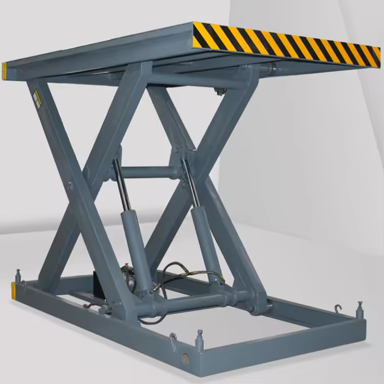
Selecting a scissor lift hydraulic cylinder starts with the lifting mechanism, not a cylinder catalog. Payload alone cannot determine the required force: cylinder mounting geometry, moving component weights, stroke, available pressure and operating speed all affect the result.
This guide is intended for designers who need an accessible route from basic data to preliminary cylinder sizing. It explains how to prepare inputs, calculate candidate dimensions and identify the questions that a cylinder supplier and mechanical designer must resolve.
All numerical examples are instructional assumptions, not purchasing specifications for a validated machine. Preliminary sizing must be followed by structural assessment, hydraulic circuit design and complete machine safety verification before manufacture and use.
1. Understand Hydraulic Cylinder Dimensions and Units
Cylinder components and the four essential dimensions
A hydraulic cylinder works much like a robust syringe: hydraulic oil acts on a movable piston inside the barrel, driving the attached piston rod. The cylinder converts hydraulic pressure into linear force; the scissor mechanism converts that movement into platform lift.1
| Parameter | Meaning | Main selection concern |
|---|---|---|
Bore D |
Internal cylinder diameter, not barrel outside diameter | Force at a given pressure |
Rod diameter d |
Diameter of the projecting piston rod | Strength and buckling resistance |
Stroke S |
Available piston rod travel | Required mechanism movement |
| Retracted mounting length | Distance between mounting pin centers when fully retracted | Whether the cylinder fits |
Bore and rod diameter address force and strength; stroke and mounting length address movement and packaging. Supplier drawings also specify mounting eyes, pin bores and ports.2
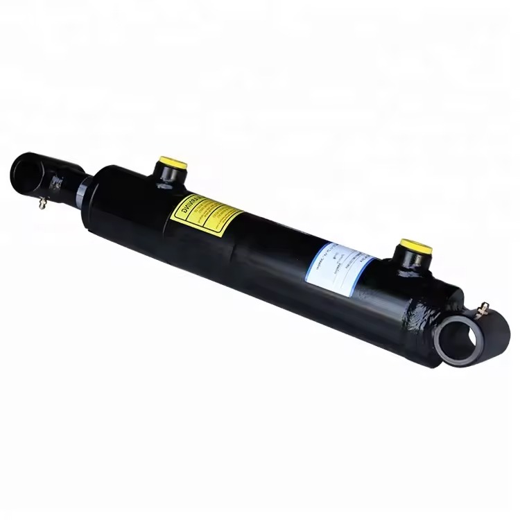
Check the supplier drawing for bore, rod diameter, stroke and mounting dimensions; the photograph alone does not establish these specifications.
Mass, force and pressure are different quantities
| Quantity | What it describes | Common units |
|---|---|---|
| Mass | How much material or payload is present | kg |
| Force | How hard the cylinder must push | N, kN |
| Pressure | Force per unit area in the hydraulic fluid | MPa, bar |
Use 1 kN = 1000 N, 1 MPa = 10 bar and g = 9.81 m/s². Pressure calculations below use MPa; do not insert a bar value directly.
For a 1000 kg payload, W = 1000 × 9.81 = 9810 N = 9.81 kN. This is its gravitational force, not the required cylinder thrust, because the scissor mechanism changes the force–displacement relationship.
2. Prepare the Scissor Lift Design Inputs
Complete the design information before selecting a cylinder. Precise arithmetic cannot compensate for incomplete inputs.
| Input | Required information | Typical source |
|---|---|---|
| Rated payload | Maximum payload in kg | Operating requirements |
| Platform mass | Platform and accessories moving with it | Drawing estimate or weighing |
| Scissor arm mass | Mass by stage and arm group | Drawing estimate or weighing |
| Minimum and maximum platform heights | Fully lowered and raised heights | Design drawing |
| Mechanism geometry | Number of stages, arm lengths and pivot locations | Side view or 3D model |
| Cylinder quantity | One, two or more | Mechanism design |
| Cylinder mounting points | Centers of the two mounting pins | Drawing or model |
| Raising time | Seconds to reach full height | Operating requirements |
| Lowering requirements | Time and whether powered retraction is needed | Operating requirements |
| Duty cycle | Cycles per hour and operating hours per day | Operating requirements |
| Power unit | Pressure, flow and motor power | Nameplate or design requirements |
| Environment | Temperature, indoor/outdoor use, water, dust and corrosion | Site conditions |
| Load position | Centered or potentially eccentric | Actual use |
| Intended use | Goods lifting, personnel lifting or other service | Product definition |
These inputs affect force, installation, service life, sealing and safety. “One-ton capacity” is insufficient.2
If drawings are incomplete, begin with a side view showing the base, platform, every scissor arm, pivots, track rollers and both proposed cylinder mounting points. Show the lowest and highest positions. Mounting points determine force, stroke and clearance, so their positions must be established deliberately.3
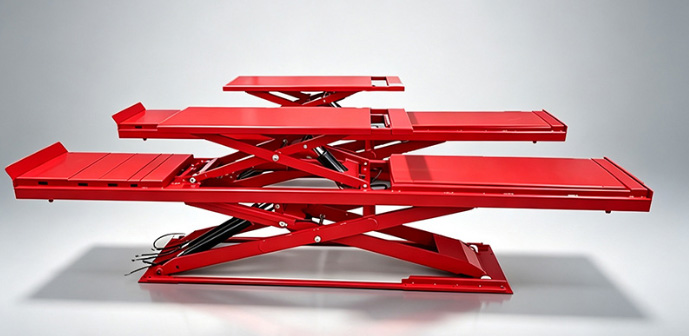
Actual scissor mechanisms differ in platform arrangement and cylinder installation. Calculate from the geometry of the intended machine.
3. Calculate Cylinder Stroke and Mounting Length
Call the cylinder mounting pin centers A and B. Measure their center distance in the mechanism model throughout the motion.
For an example in which that distance increases continuously during raising:
Lowest working position: 650 mm
Highest working position: 1050 mm
Required working stroke: 1050 - 650 = 400 mmHere l is mounting center distance. Platform lift height is not cylinder stroke. Their relationship depends on the scissor geometry and mounting points.3
If mounting distance is not monotonic, inspect intermediate positions to find its actual minimum and maximum and determine where extension or retraction is required. The subsequent example assumes continuous extension produces continuous raising.
Working stroke is also different from the final ordered stroke. Manufacturing tolerances, end clearances, travel stops and cushioning must be considered. For a 400 mm working movement, check whether the installed low position reaches the cylinder’s internal end stop, whether the upper position retains the specified allowance, whether the structure collides or the cylinder remains forced against an end stop, and whether the supplier’s retracted and extended center distances match. Do not add an arbitrary universal allowance.2
Check the full travel for barrel contact with arms or crossmembers, free rotation at both cylinder ends, port and fitting space, hose clearance, stretching or pinching, and excessive retracted length. A cylinder with enough stroke can still be impossible to install.
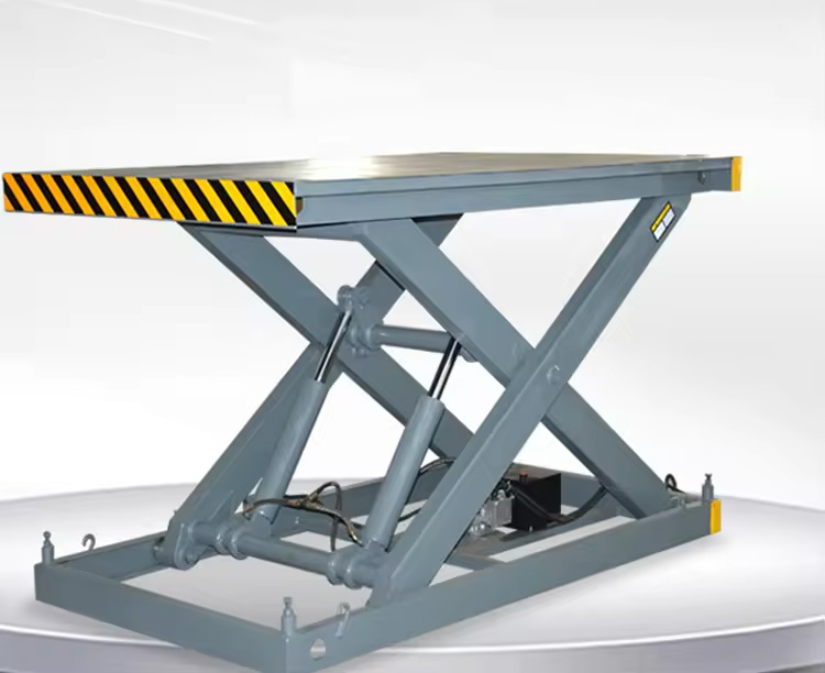
Check cylinder, mounting and hose clearances over the complete movement, including the fully lowered position.
Prefer measurements in drawings or models. If work on a raised machine is necessary, use its specified mechanical supports; hydraulic pressure alone must not support the platform during such work.4
4. Use the Local Motion Ratio to Understand Lifting Force
Why a small cylinder movement can require a large force
Suppose the platform rises 10 mm while the cylinder extends 2 mm. The platform travels five times as far. Ignoring friction and considering a load that moves with the platform, ideal work balance gives:
F is cylinder thrust, W is the gravitational force of that load, ΔH is its platform rise and Δl is the cylinder length change in the same small movement. The symbol Δ means a change.
The cylinder therefore needs about five times the platform-side gravitational force in this example. This is the virtual work principle: force and displacement are exchanged without creating energy.3
Define the local motion ratio as:
For the example, r = 10 ÷ 2 = 5. This ratio normally changes with mechanism position.
Obtain the ratio from a drawing or model
At a chosen position, record platform height H1 and cylinder center distance l1. Move the mechanism a small amount, record H2 and l2, and calculate (H2-H1)/(l2-l1). Repeat throughout travel.
| Position | Platform rise ΔH |
Cylinder extension Δl |
Local ratio |
|---|---|---|---|
| Near the lowest position | Record | Record | ΔH/Δl |
| Lower position | Record | Record | ΔH/Δl |
| Mid-travel | Record | Record | ΔH/Δl |
| Upper position | Record | Record | ΔH/Δl |
| Near the highest position | Record | Record | ΔH/Δl |
These five positions illustrate a record format, not a sufficient sampling rule. Add points where geometry changes rapidly and reduce step size until results no longer change appreciably.
If the platform rises while cylinder length barely changes, the installation may require very high force. Reconsider the geometry rather than attempting to solve it by unlimited pressure increases.
Many scissor mechanisms require high starting thrust near the folded position, but the actual peak depends on the mounting layout. Check the entire stroke. Total platform rise divided by total cylinder stroke is an average ratio and cannot replace the local ratio.
5. Calculate Required Hydraulic Cylinder Thrust
Include all moving masses and their center-of-gravity paths
The cylinder lifts the payload, platform, accessories, scissor arms and other rising parts. Their centers of gravity may rise by different distances. A fixed base does not itself gain gravitational potential energy, although its weight still matters for base loading and machine stability.
The center of gravity is the location at which a component’s weight can be treated as acting. It is generally at the midpoint of a uniform straight arm; attachments require an actual mass distribution assessment.
For one cylinder during a small, slow upward movement:
For an infinitesimal movement:
m_i is each moving mass and Δz_i its center-of-gravity rise. Use the same length units throughout the ratio. These expressions exclude friction and acceleration.3
Simplify with an equivalent platform mass
Where the center-of-gravity motion ratios are known:
Equivalent mass is a calculation quantity, not the machine’s actual total mass. It can vary with position if component motion ratios vary.
Assume a 1000 kg payload, 200 kg platform, 200 kg of scissor arms, one cylinder and maximum local motion ratio 5. In this simplified case, the arm centers of gravity rise by half the platform movement:
Equivalent arm mass = 200 × 0.5 = 100 kg
m_eq = 1000 + 200 + 100 = 1300 kg
F_ideal = 1300 × 9.81 × 5 = 63765 N ≈ 63.8 kNThus a 1000 kg payload needs approximately 63.8 kN of ideal thrust in this assumed mechanism, rather than approximately 9.8 kN. The half-mass treatment is specific to the assumed center-of-gravity paths; multistage scissors and different attachments require separate calculations.
Allow for mechanism losses and starting or dynamic loads
A preliminary model is:
η_link is mechanism efficiency for losses at pivots, rollers and similar locations. K_d is the adopted starting or dynamic load factor.
Assume η_link = 0.85, meaning roughly 85 of every 100 units of input work contribute to ideal lifting, and K_d = 1.20, a 20% dynamic increase:
F_req = 63.765 ÷ 0.85 × 1.20 ≈ 90.0 kNNeither 0.85 nor 1.20 is a universal recommended value. Select them from actual friction, starting behavior, acceleration, duty and applicable requirements. Fast or impact-loaded motion needs more detailed dynamic analysis. These factors do not replace structural strength and stability safety factors.
Calculate required force over the complete stroke and take the peak for the design load cases. Engineering review and subsequent testing must confirm whether the model is adequate.
Multiple cylinders require verified load sharing
Divide force equally only where motion and load distribution are assured. Eccentric loading, structural skew and unequal movement can overload one cylinder. Check load sharing and synchronization together.
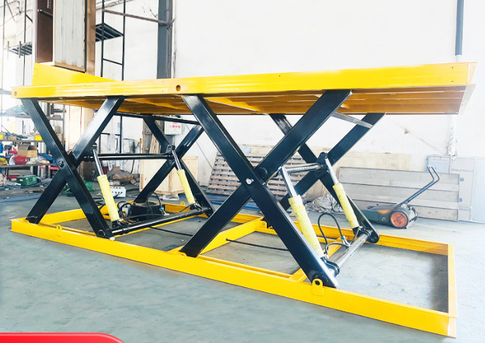
Several cylinders do not automatically share the load equally. Verify mounting geometry, eccentric loading and synchronization.
6. Size the Cylinder Bore from Force and Available Pressure
Basic force–area relationship
With negligible return-side pressure and friction:
Use π = 3.1416, F in N, p in MPa, A in mm² and D in mm. Since 1 MPa = 1 N/mm², MPa × mm² = N. Convert kN to N by multiplying by 1000 before substitution.1
Cylinder seals introduce their own friction, separate from mechanism losses. With negligible back pressure, a preliminary cylinder mechanical efficiency η_c gives:
Actual friction need not be a constant percentage; verify supplier performance data.
Compare candidate bores
For F_req ≈ 90021 N, pressure available at the cylinder p = 16 MPa, and η_c = 0.90:
D_min = √[4 × 90021 ÷ (3.1416 × 16 × 0.90)] ≈ 89.2 mmSelect an available candidate above the calculated minimum, then continue verification.2
| Bore | Piston area | Theoretical thrust at 16 MPa | Estimated thrust at efficiency 0.90 |
|---|---|---|---|
| 80 mm | 5027 mm² | 80.4 kN | 72.4 kN |
| 90 mm | 6362 mm² | 101.8 kN | 91.6 kN |
| 100 mm | 7854 mm² | 125.7 kN | 113.1 kN |
These are comparison diameters, not a statement of every supplier’s available range. Increasing diameter from 80 to 100 mm is a 25% increase in diameter and approximately 56% in area and theoretical force at the same pressure.
A 100 mm bore is a candidate for further checks, not a complete purchase specification. Rod diameter, space, pressure rating and service life remain unresolved.
Use pressure actually available at the cylinder
Valves, hoses and fittings cause pressure losses between the power unit and the cylinder. Bore sizing must use pressure actually achievable at the cylinder inlet.
Rated working pressure differs from test pressure, and permissible short pressure peaks differ from continuous operating pressure. If the system is not yet specified, choose pressure and bore together. The example’s 16 MPa is an input assumption, not a standard recommendation.2
Include rod-side back pressure where relevant
The more complete extension force balance is:
Here p1 is cap-end pressure, A1 = πD²/4 is full piston area, p2 is rod-end pressure, and A2 = π(D²-d²)/4 is annular area. The cap end is the piston side without the projecting rod; the rod end contains the rod.
Ask the supplier to verify this balance against the circuit, particularly where throttling or load control valves create back pressure.
7. Verify Piston Rod Buckling and Mounting Loads
A slender rod may bend sideways under compression before its material crushes. This is buckling. Rod diameter, extended length, support conditions, eccentricity and lateral loads all affect it. Choosing rod diameter as half the bore does not replace a strength and stability calculation.5
Provide the supplier with force throughout travel, maximum working stroke, extended lengths and mounting distances at relevant positions, end support and rotation details, and potential eccentric or lateral loading. Request the proposed rod diameter and the supporting buckling calculation.
Do not equate stroke with the full effective compression length. The mounting arrangement determines the appropriate model. ISO/TS 13725 describes an assessment method for certain hydraulic cylinders with defined applicability; use a method suited to the actual cylinder and its boundary conditions.5
Check the low position for starting force, the high position for long extension, and intermediate positions for a potentially worse force–length combination.
Cylinder thrust passes through mounting eyes, pins, brackets, welds and scissor arms. Verify pin shear and bending, bearing stress around holes, bracket and weld capacity, side loading and fatigue under repeated cycles. A compliant cylinder does not establish that custom mounts or arms are adequate.
Structural loads cannot be based only on the example’s 90 kN requirement. Actual maximum system pressure may generate a greater cylinder force. Include jamming, travel stops and other load cases.2
8. Match Cylinder Speed, Pump Flow and Motor Power
Pressure determines force; flow determines speed
Pressure and piston area determine lifting force. Flow and piston area determine rod speed. Increasing pump flow does not correct inadequate force at the available pressure.1
The inlet oil volume for one cylinder’s extension is:
With A in mm² and actual working stroke S in mm, V is in L. The divisor converts mm³ to L.
For a 100 mm bore and 400 mm working stroke:
A = 3.1416 × 100² ÷ 4 ≈ 7854 mm²
V = 7854 × 400 ÷ 1000000 ≈ 3.14 LThis is the cap-end oil volume added during that movement, not the required reservoir capacity.1
For completion in t seconds:
At t = 30 s, Q = 60 × 3.14 ÷ 30 ≈ 6.28 L/min. This is the required inlet flow; pump selection must also allow for actual losses and circuit requirements.
For n identical cylinders completing the same extension stroke together:
This volume calculation does not establish synchronization.
Constant rod speed does not ensure constant platform speed
For the single-cylinder case with continuous extension during raising:
v_H is platform speed and v_c rod extension speed, expressed in matching units. Because r varies with position, constant cylinder speed can produce increasing or decreasing platform speed. Uniform platform speed requires coordinated mechanism and flow control design.
Estimate pump shaft power at the operating point
Use pump outlet pressure p in MPa, pump output flow Q in L/min, pump overall efficiency η_p, and power in kW.
With assumed pump outlet pressure 16 MPa, flow 6.28 L/min and efficiency 0.80:
P_shaft = 16 × 6.28 ÷ (60 × 0.80) ≈ 2.09 kWThis estimate applies to that pressure–flow combination. Bore sizing used pressure at the cylinder; the final power unit design must include pressure losses from pump to cylinder. Do not assume the two pressures are always equal.
Select the motor from actual maximum operating conditions, starting requirements, duty and temperature rise. The 2.09 kW result alone does not determine a motor model.
9. Choose Return Operation, Load Holding and Lowering Control
| Cylinder type | Operating principle | Required checks |
|---|---|---|
| Single-acting | Hydraulic pressure drives one direction; gravity or another external force returns it | Reliable return unloaded, at low temperature and throughout travel |
| Double-acting | Hydraulic pressure can drive both directions | Extension and retraction forces, flow and control |
A heavy platform does not guarantee gravity lowering at every position. A double-acting cylinder retracts using the annular area, so at equal pressure its ideal pull force is normally smaller than its extension force.2
Define how the load is held after controls are released, permissible drift over a specified time, behavior with directional valve leakage, and protection against uncontrolled movement if a hose fails.
Choose valves for the actual load-holding and controlled-lowering circuit. Where a component protects against failure of a particular hose section, its location must allow it to protect that section; placement near or integrated into the cylinder is common.6
| Component | Typical purpose |
|---|---|
| Pilot-operated check valve | Blocks reverse flow and holds position |
| Counterbalance or load control valve | Holds and controls motion under defined load conditions, limiting load-driven runaway |
| Hose rupture protection device | Protects against specified line failure scenarios |
Holding still and lowering smoothly are separate tasks. These components are not interchangeable solely by name, and one valve must not be assumed to cover every failure mode.6
Before personnel work below a raised platform or inside the scissor hazard zone, use the specified mechanical supports and isolation measures. Mechanical support means a physical structure carrying the load, not merely a hydraulically locked cylinder.4
Goods lifts, personnel platforms, fixed equipment and mobile equipment have different whole-machine requirements. Determine applicable standards from the actual use and operating region.
10. Complete Worked Example: Preliminary Sizing for a 1000 kg Payload
Every input below is instructional and does not describe a verified machine.
| Input | Assumption |
|---|---|
| Payload / platform / total arm mass | 1000 / 200 / 200 kg |
| Arm center-of-gravity rise | Half the platform rise |
| Cylinder quantity | 1 |
| Maximum local motion ratio over travel | 5, assumed confirmed by the model |
| Mechanism efficiency / dynamic factor | 0.85 / 1.20 |
| Available cylinder pressure / cylinder efficiency | 16 MPa / 0.90 |
| Minimum / maximum working center distance | 650 / 1050 mm |
| Length change during raising | Continuously increasing |
| Raising time | 30 s |
Calculate in this order:
1. Working stroke:
S_work = 1050 - 650 = 400 mm
2. Equivalent mass:
m_eq = 1000 + 200 + 200 × 0.5 = 1300 kg
3. Ideal thrust:
F_ideal = 1300 × 9.81 × 5 = 63765 N ≈ 63.8 kN
4. Required thrust:
F_req = 63765 ÷ 0.85 × 1.20 ≈ 90021 N ≈ 90.0 kN
5. Minimum calculated bore:
D_min = √[4 × 90021 ÷ (3.1416 × 16 × 0.90)] ≈ 89.2 mm
6. Check a 100 mm candidate:
A ≈ 7854 mm²
F_available ≈ 16 × 7854 × 0.90 ≈ 113097 N ≈ 113.1 kN
7. Inlet volume and flow:
V = 7854 × 400 ÷ 1000000 ≈ 3.14 L
Q = 60 × 3.14 ÷ 30 ≈ 6.28 L/minThe candidate passes this simplified thrust comparison because 113.1 kN > 90.0 kN.
| Preliminary result | Value |
|---|---|
| Candidate bore | 100 mm |
| Required working stroke | 400 mm |
| Required working center distances | 650–1050 mm |
| Peak required single-cylinder thrust | Approximately 90.0 kN under the assumptions |
| Inlet flow for a 30-second extension | Approximately 6.28 L/min |
| Unresolved item | Remaining work |
|---|---|
| Rod diameter | Strength and buckling calculation |
| Complete installation dimensions | Supplier drawing and end allowances |
| Rated pressure and permissible peaks | Complete system pressure limits |
| Mounting connections | Pins, supports and weld design |
| Lowering and load holding | Detailed hydraulic circuit |
| Motor specification | Actual pump pressure, losses and duty |
| Final machine rating | Structural, stability and whole-machine validation |
These results support a supplier discussion. “100 mm bore, 400 mm stroke” is not a complete purchasing specification.
11. Prepare the Supplier Specification and Validation Plan
Information to provide or confirm
| Category | Supplier information |
|---|---|
| Application | Scissor lift table; fixed/mobile; goods/personnel |
| Drawings | Side view, mounting points, lowest and highest positions |
| Loading | Rated payload, platform and moving masses, eccentric loading |
| Thrust | Required force over travel, peak value and its location |
| Candidate dimensions | Bore, working stroke and mounting distance limits |
| Rod | Supplier’s proposed diameter and buckling justification |
| Pressure | Normal operating pressure, actual system maximum and possible peaks |
| Speed | Raising/lowering times and speed uniformity requirement |
| Mounting | Eyes, pin bores, pins, bearings and allowable rotation |
| Interfaces | Ports, fittings, valve block positions and space limits |
| Environment | Temperature, hydraulic fluid, dust, water and corrosion |
| Duty | Cycles per hour, hours per day and holding time |
| Holding and lowering | Permissible drift, lowering control and line failure protection |
| Deliverables | Dimensional drawings, performance data, calculations and test records |
Define engineering responsibilities
The cylinder supplier covers cylinder dimensions, push/pull performance, pressure rating, seals, rod stability and cylinder quality. The mechanical designer covers scissor forces, mounting geometry, pins, supports, welds, guiding and stability. The hydraulic designer covers the power unit, valves, piping, holding, lowering, pressure limits and thermal loading. The machine-responsible party covers intended use, applicable standards, risk assessment, verification and final rated capacity.
One team may perform several roles, but a supplier’s force confirmation does not remove any of these responsibilities.
Verify the prototype against a formal plan
Qualified personnel should check unloaded movement; reliable starting from the lowest position at rated load; actual pressure over travel; raising and lowering speeds; tilt, jamming and synchronization under specified eccentric loads; drift and leakage while holding; temperature rise during continuous operation; power-loss, emergency-stop and controlled-lowering behavior; and specified protective functions.
Load tests, overload tests and fault protection tests require applicable standards and a formal procedure. Beginners must not improvise loaded hose rupture tests or enter hazardous zones.
12. Avoid Common Scissor Lift Cylinder Selection Errors
| Misconception | What must be corrected |
|---|---|
| A one-ton payload needs one-ton cylinder thrust | Include mechanism leverage and moving masses |
| Mounting position makes no difference | It changes force, stroke and available space |
| Only the highest position needs checking | Check the entire travel for peak demand |
| Total rise / total stroke is sufficient for force sizing | It hides local peaks |
| Enough stroke guarantees installation | Check retracted length, eyes, fittings and interference |
| Rod diameter can simply equal half the bore | Perform strength and buckling checks |
| Two cylinders automatically split the load equally | Verify eccentric loading and synchronization |
| More pump flow lifts a heavier load | Flow mainly changes speed; pressure and area determine force |
| A larger bore is always better | It increases volume, space and cost and affects speed and structural maximum force |
| High test pressure is a continuous working rating | Distinguish test, working and peak pressures |
| A holding valve makes work under the platform acceptable | Use specified mechanical supports |
| This example is a universal one-ton lift specification | Recalculate for the actual geometry and conditions |
Appendix A. Hydraulic Cylinder Calculation Reference
| Purpose | Formula | Units or conditions |
|---|---|---|
| Gravitational force | W = mg |
kg, 9.81 m/s², result N |
| Working stroke | S_work = l_max-l_min |
Center distances over complete travel |
| Local motion ratio | r ≈ ΔH/Δl |
Same movement and matching length units |
| Ideal single-cylinder thrust | F_ideal ≈ gΣ(m_iΔz_i)/Δl |
Slow motion; excludes friction and dynamics |
| Equivalent mass method | F_ideal ≈ m_eq g r |
Correct component motion weighting |
| Preliminary required thrust | F_req = K_d F_ideal/η_link |
Factors require justification |
| Cap-end area | A = πD²/4 |
D in mm; area in mm² |
| Ideal extension force | F = pA |
MPa, mm², N; no back pressure or friction |
| Preliminary minimum bore | D_min ≈ √[4F_req/(πpη_c)] |
N, MPa, result mm |
| Rod-end annular area | A2 = π(D²-d²)/4 |
D and d in mm; area in mm² |
| Net extension force | F_net = p1A1-p2A2-F_friction |
Both chamber pressures and friction |
| Extension inlet volume | V = AS/10⁶ |
mm², mm, result L |
| Inlet flow | Q = 60V/t |
L, s, result L/min |
| Pump shaft power | P_shaft ≈ pQ/(60η_p) |
Pump outlet MPa, L/min, result kW |
Appendix B. Fill-in Cylinder Selection Record
Inputs
Maximum payload: ________ kg
Platform and accessory mass: ________ kg
Arm mass by group: ________ kg
Other moving masses and locations: ________________
Minimum / maximum platform height: ________ / ________ mm
Cylinder quantity and mounting points: ________________
Minimum / maximum mounting center distance: ________ / ________ mm
Cylinder length increases continuously during raising: yes / no / confirm
Raising time: ________ s
Lowering requirements: ________________
Cycles per hour: ________
Available cylinder pressure: ________ MPa / confirm
Existing power unit flow: ________ L/min / confirm
Temperature and environment: ________________
Load eccentricity: ________________
Intended use and personnel lifting: ________________Intermediate calculations
Required working stroke: ________ mm
Local motion ratios over travel: see calculation record
Moving component center-of-gravity paths: see drawing/model
Peak ideal thrust: ________ kN at position ________
Basis for mechanism losses: ________________
Basis for starting or dynamic loads: ________________
Peak required thrust for design conditions: ________ kNCandidate cylinder
Candidate bore: ________ mm
Candidate rod diameter: ________ mm / verify
Candidate cylinder stroke: ________ mm
Fully retracted / extended mounting center distance: ________ / ________ mm
Rated working pressure: ________ MPa
Actual system pressure maximum: ________ MPa / confirm
Required inlet flow: ________ L/min
Mounting connections and ports: ________________
Holding, lowering and line failure protection: ________________Completion checklist
- Required force calculated throughout travel.
- End allowances, stops and retracted length checked.
- Barrel, fittings and hoses clear throughout motion.
- Rod diameter and buckling verified.
- Pins, supports, welds and scissor structure verified.
- Eccentric loading, load sharing and synchronization addressed.
- Power unit pressure, flow, power and duty matched.
- Holding, lowering, mechanical supports and protection designed.
- Applicable whole-machine requirements and prototype test plan confirmed.
References
These references support the principles and assessment methods. The example and assumptions belong to this article; citation does not mean the sources approve them for machine manufacture.
Footnotes
-
Parker, Mobile Cylinder Products and Application Guide, formula section: force, piston area, oil volume and speed. Official PDF. ↩ ↩2 ↩3 ↩4
-
Parker / Miller Fluid Power, MHP Series Metric Hydraulic Cylinders: engineering data, push/pull forces, rod selection and mounting dimensions. Official PDF. This historical catalog illustrates selection methods; obtain current supplier confirmation of specifications, availability and permitted conditions. ↩ ↩2 ↩3 ↩4 ↩5 ↩6 ↩7
-
Mechanical simulation and installation position optimisation of a lifting cylinder of a scissors aerial work platform, DOI: 10.1049/joe.2018.8961. Virtual work modeling and mounting-position effects. Paper. ↩ ↩2 ↩3 ↩4
-
JLG, 260MRT Operation Manual, safety prop and maintenance sections. The reference supports mechanical support principles, not direct adoption of this model’s procedures for a custom lift. Official PDF. ↩ ↩2
-
ISO/TS 13725:2021, Hydraulic fluid power — Method for evaluating the buckling load of a hydraulic cylinder. Check method applicability to the actual cylinder. ISO information. See also Hänchen’s mounting and buckling calculation information. ↩ ↩2
-
Danfoss, Motion control valves, load holding and motion control information. See also Valmet’s counterbalance valve technical article. ↩ ↩2
For more information about our hydraulic cylinder manufacturing, projects and services, please contact the Elephant Machinery team.
Contact our team