

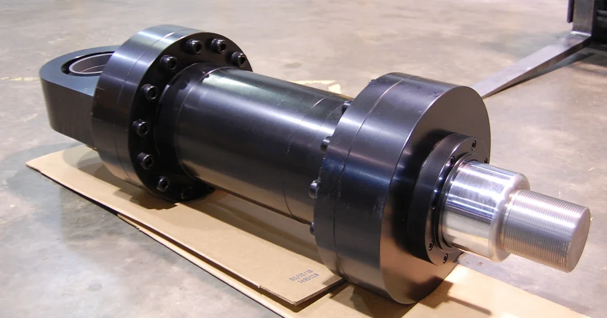
A practical sizing workflow covering force calculations, piston rod diameter, seals, cushioning and operating conditions
Summary: Reliable hydraulic cylinder selection starts with the application, then connects load and pressure to bore and rod size. This guide explains the calculation process, reproduces the source reference tables, and brings stroke, mounting, cushioning, fluid, seals and auxiliary features into one selection workflow.
A hydraulic cylinder converts hydraulic power into mechanical motion. Its suitability therefore depends on more than rated force: it must fit the machine, withstand its operating conditions and move the load as intended. Precision machine tools and heavily loaded construction equipment place very different demands on the same basic component.
An unsuitable cylinder can reduce efficiency, cause recurring failures and create safety risks. A sound selection process follows the load through the system: establish the duty, choose pressure, calculate dimensions, then check how the cylinder will be mounted, controlled and protected.
The numerical guidance below comes from the supplied article. Apply it as reference information for the relevant cylinder and application; the source’s incomplete entries and technical ambiguities are identified in the editorial notes.
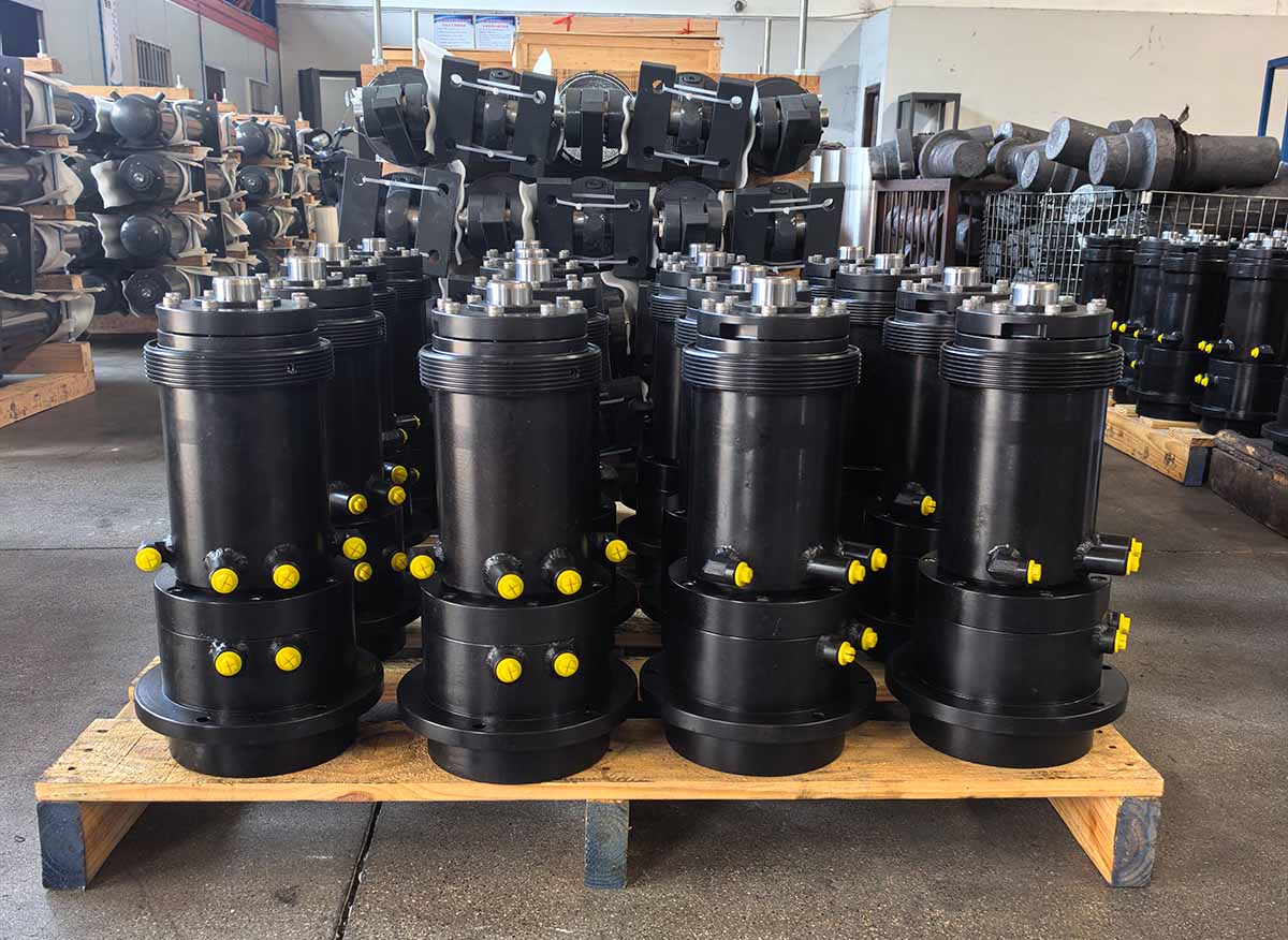
1. Start with the operating conditions
Record the required pushing and pulling forces, motion, available installation space and working environment before selecting a cylinder series. Several conditions influence the seals, materials and structural details together.
| Operating condition | Points to check |
|---|---|
| High positioning or motion accuracy | For servo cylinders and other medium-to-high-pressure cylinders requiring low breakaway pressure, examine the sealing system, component materials and detailed design. |
| Specified pressure holding or zero-leakage requirements | Assess the sealing arrangement and material properties against the actual requirement. |
| Medium- or low-pressure operation at piston reciprocating speeds stated as ≥70–80 mm/s | Review seals, materials, connecting structures and fit accuracy. |
| Medium-to-high or high-pressure operation at reciprocating speeds stated as ≥100–120 mm/s | Give the same attention to seals, materials, connections and fit accuracy. |
| High-frequency vibration | Check material properties, connecting structures and design details. |
| Low-temperature icing, contamination or high dust levels | Evaluate seals, materials, piston rod surface treatment and overall protection. |
| Water spray, acid mist or salt mist | Evaluate the same features, with particular attention to surface protection. |
Fluid, temperature and cleanliness
Mineral oil is the normal working fluid described in the source. If another fluid is used, check its effect on the seals and every component material.
The article recommends No. 32 and No. 46 anti-wear hydraulic oils. Its preferred oil temperature is 20–55 °C, and it prohibits operation with oil below 15 °C or above 70 °C. Preheating or cooling can be used to bring the oil into the required range. It also gives an oil replacement interval of 1–6 months, accompanied by tank cleaning and removal of contamination.
Keep the fluid clean and prevent deterioration. The source warns that contamination can clog the suction filter, increase noise and shorten pump life.
A separate reference range of −20 to +80 °C is given for the normal working environment or medium temperature. Outside that range, review the seals, component materials and cooling arrangements. This broader range must not be read as overriding the narrower oil operating limits above.
2. Match system pressure to the load and machine
Pressure selection starts with load F, but installation space, cost and component availability also matter.
At a fixed load, lower pressure requires a larger effective piston area. The cylinder becomes larger, which can conflict with space restrictions and increase material use. Higher pressure reduces the required area but raises the demands on the pump, cylinder, valves, seals and manufacturing precision. Equipment cost can rise accordingly.
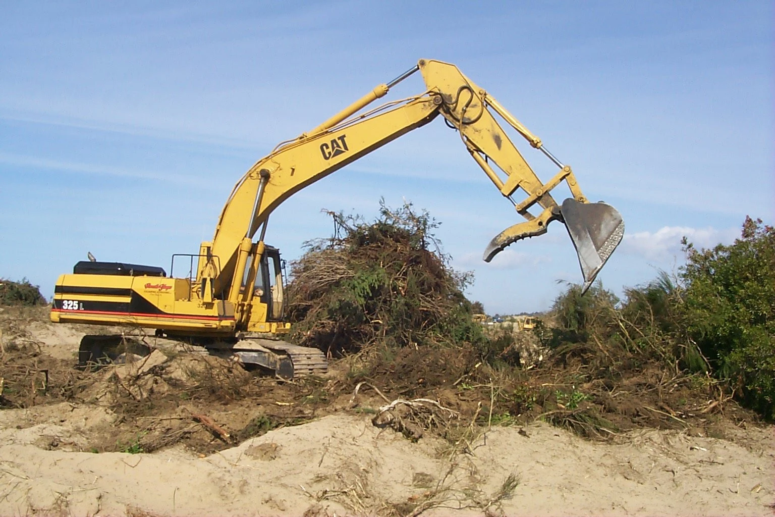
For stationary equipment with generous space, the source favors relatively low pressure. Mobile and heavily loaded machinery generally calls for higher pressure.
Reference pressure by load and machine type
Load-based reference values
| Load (t) | Working pressure (MPa) |
|---|---|
| 0.5 | 0.1–1 |
| 0.5–1 | 1.5–2 |
| 1–2 | 2.5–3 |
| 2–3 | 3–4 |
| 3–5 | 4–5 |
| 5 | Greater than [value missing in source] |
Machine-based reference values
| Machine type | Design pressure (MPa; inferred unit) |
|---|---|
| Finishing machine tools, e.g. grinding machines | 0.8–2 |
| Semi-finishing machine tools | 3–5 |
| Planing machines | 2–8 |
| Broaching machines | 8–10 |
| Agricultural machinery; small construction machinery | 10–16 |
| Hydraulic presses; medium and large excavators; medium-sized machinery; lifting and handling machinery | 20–32 |
| Geological equipment; metallurgical machinery; railway maintenance machinery | 25–100 |
The source machine-type table does not print a pressure unit. MPa is used here from the surrounding context; confirm it before engineering use.
The source also offers generally ≤21 MPa as a preliminary selection guideline. Its machine-type table includes higher pressures, so this is a contextual rule of thumb rather than a limit applying to every listed application.
3. Calculate bore diameter, then select the piston rod
Once the design pressure and required force are known, calculate the effective piston area and use it to obtain the bore. The source uses:
Extension force:  F1 = A1 × P1 × β
Retraction force: F2 = A2 × P2 × β

A1 = (π/4) × D² = 0.785 × D²
A2 = (π/4) × (D² − d²) = 0.785 × (D² − d²)| Symbol | Meaning | Unit or definition |
|---|---|---|
| F1 | Extension/pushing force | kgf in this calculation system |
| F2 | Retraction/pulling force | kgf in this calculation system |
| A1 | Effective piston area on the extension side | cm² |
| A2 | Effective annular area on the retraction side | cm² |
| D | Cylinder bore, equal to piston diameter | cm |
| d | Piston rod diameter | cm |
| P1 | Operating pressure on the extension side | kgf/cm² |
| P2 | Operating pressure on the retraction side | kgf/cm² |
| β | Load factor used by the source | 0.8 for low-inertia duties; 0.6 for high-inertia duties |
Actual cylinder force is lower than theoretical force. The source accounts for this in its sizing method by using β = 80% for low-inertia applications and β = 60% for high-inertia applications. Do not apply this factor to the theoretical force tables and still label the result theoretical.
Worked example: select a bore for a force of 1,000 kgf
The source states a required output of “1,000 kg,” an operating pressure of 70 kgf/cm², and β = 0.8. For dimensional consistency, that output is expressed here as 1,000 kgf.
A1 = F1 / (P1 × β)
   = 1,000 / (70 × 0.8)
   = 17.86 cm²

D² = 17.86 / 0.785 = 22.75 cm²
D  = √22.75 ≈ 4.8 cm = 48 mm

Selected standard bore: 50 mm
Choose a standard bore size. The source notes that a smaller bore can reduce cost; it must still provide the required force.
It also gives the pressure-area relationship:
P = 4F / (π × D²)This form uses the circular piston area. Keep units consistent and distinguish it from the earlier sizing formula that explicitly includes β.
Preliminary rod-to-bore ratios
| Pressure P | Preliminary piston rod diameter d |
|---|---|
| P ≤10 MPa | d = 0.5D |
| P = 12.5–20 MPa | d = 0.56D |
| P >20 MPa | d = 0.71D |
The source does not specify a ratio for 10 < P <12.5 MPa. Do not silently interpolate that missing interval.
Theoretical extension and retraction force tables
The original combined table is separated below for readability. Bore and rod diameters are in mm; pressure headings are in kgf/cm². The original output heading is “kg”; values are reproduced unchanged and interpreted as kgf in this force context. The tables do not include β. Some source entries require verification before use.
Theoretical retraction/pulling force (kgf)
Pressure in each column: kgf/cm². D = bore; d = rod diameter.
| D (mm) | d (mm) | 30 | 50 | 70 | 100 | 140 | 160 | 210 | 250 | 315 |
|---|---|---|---|---|---|---|---|---|---|---|
| 40 | 20 | 282 | 470 | 658 | 940 | 1316 | 1504 | 1974 | 2360 | 2970 |
| 50 | 25 | 441 | 435 | 1029 | 1470 | 2058 | 2352 | 3087 | 3680 | 4640 |
| 63 | 30 | 723 | 1205 | 1687 | 2410 | 3374 | 3856 | 5601 | 6030 | 7600 |
| 80 | 40 | 1131 | 1885 | 2633 | 3770 | 5278 | 6032 | 7917 | 9430 | 11880 |
| 100 | 50 | 1767 | 2946 | 4124 | 5891 | 8247 | 9425 | 12370 | 14730 | 18560 |
| 125 | 60 | 2833 | 4722 | 6611 | 9444 | 13222 | 15110 | 19830 | 23610 | 29750 |
| 150 | 70 | 4147 | 6911 | 9675 | 13822 | 19351 | 22115 | 29026 | 34560 | 43550 |
| 180 | 80 | 6126 | 10210 | 14295 | 20421 | 28589 | 32674 | 42884 | 51000 | 64320 |
| 200 | 100 | 7067 | 11781 | 16493 | 23562 | 32987 | 37699 | 49480 | 58900 | 74200 |
| 250 | 140 | 10108 | 16847 | 23586 | 33694 | 47172 | 53910 | 70757 | 84250 | 106100 |
| 300 | 180 | 13572 | 22620 | 31667 | 45239 | 63335 | 72382 | 95002 | 113100 | 142500 |
| 320 | 200 | 14700 | 24500 | 34300 | 49000 | 68600 | 78400 | 102900 | 122500 | 154400 |
| 350 | 220 | 17500 | 29100 | 40700 | 58200 | 81500 | 93100 | 122200 | 145500 | 183300 |
| 400 | 280 | 19200 | 32000 | 44900 | 64100 | 89700 | 102600 | 134600 | 160000 | 201900 |
Theoretical extension/pushing force (kgf)
Pressure in each column: kgf/cm². D = bore; d = rod diameter.
| D (mm) | d (mm) | 30 | 50 | 70 | 100 | 140 | 160 | 210 | 250 | 315 |
|---|---|---|---|---|---|---|---|---|---|---|
| 40 | 20 | 378 | 630 | 882 | 1260 | 1764 | 2016 | 2646 | 3150 | 3960 |
| 50 | 25 | 588 | 980 | 1372 | 1960 | 2744 | 3136 | 4116 | 4910 | 6190 |
| 63 | 30 | 936 | 1560 | 2184 | 3120 | 4368 | 4992 | 6552 | 7800 | 9820 |
| 80 | 40 | 1509 | 2515 | 3521 | 5030 | 7052 | 8248 | 10563 | 12570 | 15830 |
| 100 | 50 | 2356 | 3927 | 5498 | 7854 | 11100 | 12566 | 16493 | 19640 | 24740 |
| 125 | 60 | 3682 | 6136 | 8590 | 12272 | 17180 | 19625 | 25770 | 30680 | 38660 |
| 150 | 70 | 5301 | 8835 | 12369 | 17670 | 24738 | 28272 | 37107 | 44200 | 55680 |
| 180 | 80 | 7634 | 12724 | 17813 | 25447 | 35626 | 40715 | 53439 | 63600 | 80160 |
| 200 | 100 | 9425 | 15708 | 21991 | 31416 | 43982 | 50266 | 65974 | 78500 | 99000 |
| 250 | 140 | 14726 | 22544 | 31562 | 49088 | 68723 | 72141 | 94685 | 122700 | 154600 |
| 300 | 180 | 21206 | 35343 | 49480 | 70686 | 98960 | 113097 | 118440 | 176700 | 222700 |
| 320 | 200 | 24100 | 40210 | 56300 | 80400 | 112600 | 128700 | 168900 | 201000 | 253400 |
| 350 | 220 | 28800 | 48200 | 67300 | 96000 | 134700 | 154000 | 202000 | 240600 | 303000 |
| 400 | 280 | 37700 | 62800 | 88000 | 125700 | 176000 | 201000 | 264000 | 314200 | 395800 |
4. Resolve stroke and mounting as one design problem
The required travel establishes the working stroke, but installation tolerances and end positions determine how much extra travel is needed:
S = Smax + ΔS
ΔS = ΔS1 + ΔS2 + ΔS3
Here, Smax is the actual maximum working stroke. ΔS1 covers manufacturing errors in the system’s installation dimensions; ΔS2 provides any necessary allowance at the start of travel; ΔS3 provides it at the end.
Keep the total allowance as small as practicable where cushioning is required, because the allowance directly affects cushioning behavior. For a long-stroke cylinder exceeding a series’ permitted stroke, or for a special duty, check stability against the actual load characteristics and mounting arrangement. Very short strokes must also be checked against the minimum stroke permitted by the selected series and mounting.
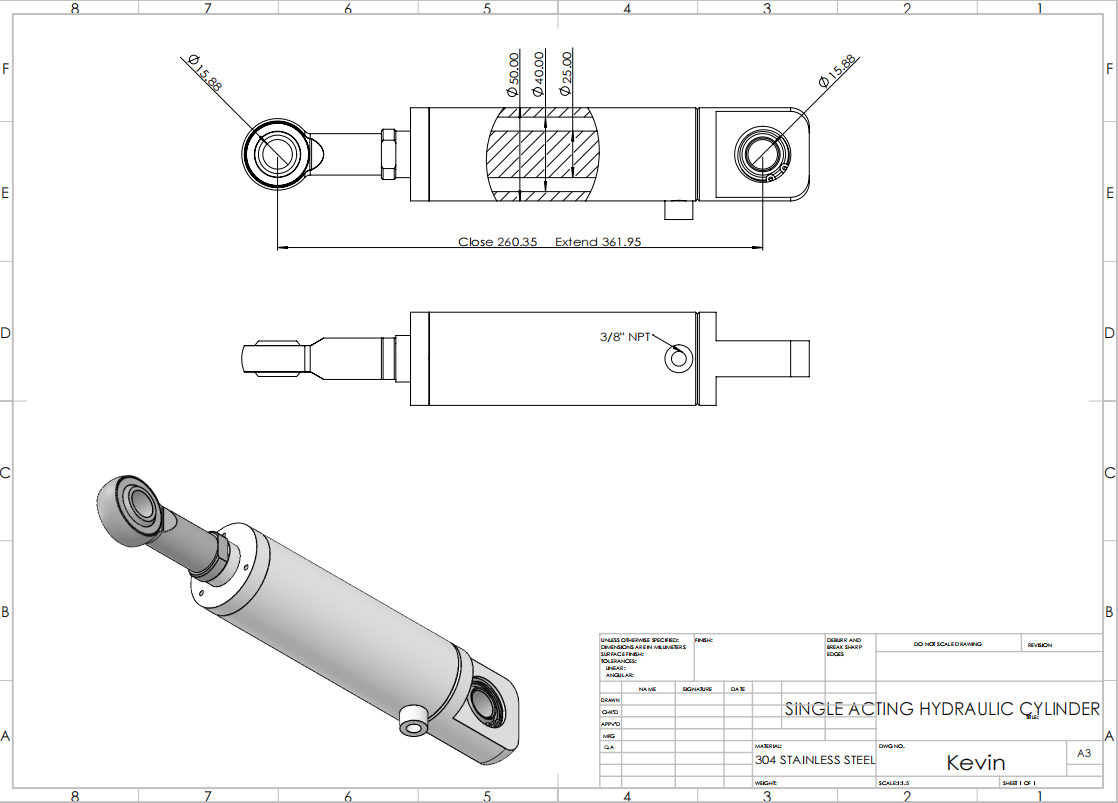
Flange mounting: align the force with the support axis
Front/end, intermediate and rear flanges provide fixed mounting for duties in which the load force and support center share an axis.
Select the flange location according to whether compression during extension or tension during retraction is the main duty. The source favors rear or intermediate flanges for compressive/pushing loads, and front/end or intermediate flanges for tensile/pulling loads. The final choice must reflect the machine structure and, for long strokes under compression, the cylinder’s buckling stability.
Pivot mounting: allow the cylinder to follow the mechanism
Rear single-eye or double-lug clevis mounts, and front, intermediate or rear trunnions, are used when the driven component follows a curved path in one plane. During angular motion, the turning effect depends on the cylinder force, linkage lever arm and angle between the linkage and cylinder mounting.
Rear eye and clevis arrangements. The source lists rear single eyes, rear double lugs, welded single eyes and welded double lugs. A rear single eye is a common pivot arrangement for limited lateral angular movement. The printed angular allowance has an ambiguous unit; see the editorial notes. Spherical plain bearings may be used at the rear and rod end, subject to their permissible compressive load.
A rear clevis can operate at different angles within one motion plane. Under long-stroke pushing loads, assess lateral loading and bending associated with the cylinder’s own weight and the rod-loading arrangement.
Trunnion arrangements. Intermediate fixed trunnions are common. Their position can be chosen to balance cylinder weight or suit the application anywhere between the front and rear ends. Trunnions are intended to carry shear rather than bending. Use rigid bearing supports of equal length on a common axis, and place the bearings as close as possible to the trunnion shoulders to minimize bending stress.
Rear trunnion selection is similar to rear-clevis selection. Front trunnions can suit cylinders that lift through a relatively small lever arm compared with intermediate or rear pivots. For long strokes, include the suspended cylinder’s weight in the assessment. The source recommends keeping the stroke of this front-trunnion arrangement within 5 times the bore diameter.
Foot mounting: control the overturning moment
Front feet, rear feet and welded feet provide fixed mounting with the mounting plane offset from the cylinder centerline. The resulting overturning moment can create substantial lateral rod loading if the cylinder is not firmly secured or the load is poorly guided.
Position and fasten the supports accurately, and provide appropriate load guidance. The source also distinguishes end and side foot arrangements.
5. Specify cushioning, ports and valve functions
End-of-stroke cushioning
The source calls for consideration of cushioning in three cases:
- The piston travels through its full stroke in both directions at speeds above 100 mm/s: select cushioning at both ends.
- The piston reaches an end position in one direction at a speed above 100 mm/s: select cushioning at the relevant end or at both ends, according to the motion.
- Other special operating conditions require it.
Port connection and passage size
Internal-thread connections, flange connections and special port forms are selected to match the system piping.
Size the port after the connecting-line flow is known. The source generally limits fluid velocity through the port to 5 m/s, while also requiring consideration of the speed ratio between extension and retraction.
Pressure holding, support and hydraulic locking
Spool directional control valves have clearance leakage, so the source treats them as suitable only for short-term pressure holding. Where longer holding is needed, a pilot-operated check valve can be added, using its tightly seated poppet closure to retain pressure in the circuit.
For vertical cylinders, leakage through the valve and piping can allow the piston and rod to descend under their own weight. A pilot-operated check valve in the line to the lower chamber can restrain downward movement of the piston and connected parts, such as a slide.
For hydraulic locking, the source describes two pilot-operated check valves. When the directional valve is in its center position, both check valves close and trap oil in the two cylinder chambers to resist displacement under external force.
6. Complete the selection with seals and auxiliary features
Select seals for the consequences of failure
Seal quality deserves particular attention in special duties, where a specified quality is required, where failure affects safety or causes major economic loss, or where replacement is difficult. Cylinders supplied with machinery for export may also have specific sealing requirements.
The source recommends that the manufacturer’s specialist engineer select established seal products with good interchangeability and ready availability, matched to the operating conditions.
Provide air bleeding where air accumulates
Depending on the cylinder’s working orientation, air bleed valves are normally positioned at the highest air-collection points in the end regions of both chambers. Bleeding the air helps prevent stick-slip, protects the seals and reduces fluid degradation.
Add a leakage drain where oil may collect
Where external oil leakage is prohibited, long strokes or particular operating conditions can allow oil to collect behind the wiper. A drain port at the collection point provides an outlet before accumulated oil escapes externally during extended operation.
7. Bring the specification together
A complete hydraulic cylinder specification connects the force calculation to the installation. Record the pressure, standard bore, rod diameter, stroke and mounting first; then define cushioning, ports, valve functions, fluid compatibility, seals, surface protection, bleeding and drainage.
Review long-stroke stability and special environmental demands together. A bore that meets the force requirement is only one part of a cylinder that fits the machine and operates reliably.
Editorial notes on the supplied data
- Incomplete load-pressure table: the last load heading reads “5,” and its pressure cell contains only “greater than,” with no numerical value. Both limitations are retained.
- Force-table discrepancies: all legible figures are retained. For example, bore 50 mm/rod 25 mm at 50 kgf/cm² lists a retraction force of 435, whereas the same row lists 441 at 30 kgf/cm². These source figures should be checked rather than silently corrected.
- Force-unit notation: the source labels forces “kg” or “kilograms.” This article uses kgf for the calculation context and identifies the original table label.
- Angular-unit ambiguity: the single-eye mounting paragraph prints “±3°C” while describing angular movement. The context suggests ±3°, but the intended unit and permitted angle require confirmation.
- Temperature and speed wording: the separate oil-temperature and environment/medium-temperature ranges are retained. The source’s threshold ranges ≥70–80 mm/s and ≥100–120 mm/s are also retained without assigning a single threshold.
- Rod-ratio gap and very short strokes: the missing 10–12.5 MPa interval is flagged. The source’s very-short-stroke item is an incomplete sentence; it is presented here only as a need to check the permitted minimum.
For more information about our hydraulic cylinder manufacturing, projects and services, please contact the Elephant Machinery team.
Contact our team