

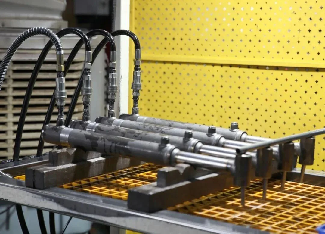
A hydraulic cylinder can pass visual and dimensional inspection and still leave essential questions unanswered. Will it withstand the specified pressure? Does oil bypass the piston seal? Is there external leakage? Does its actual stroke match the drawing?
Hydraulic cylinder factory inspection answers those questions through controlled tests. The essential requirement is a system that can control, measure, isolate and record the test conditions while providing appropriate safeguards. The test bench gives that system a practical engineering form.
GB/T 15622—2023, Hydraulic fluid power — Test methods for cylinders, is already in use, and ISO 10100:2020 covers acceptance and function tests for hydraulic fluid power cylinders. Testing therefore forms part of quality release; it is more than a demonstration that the assembled cylinder moves.
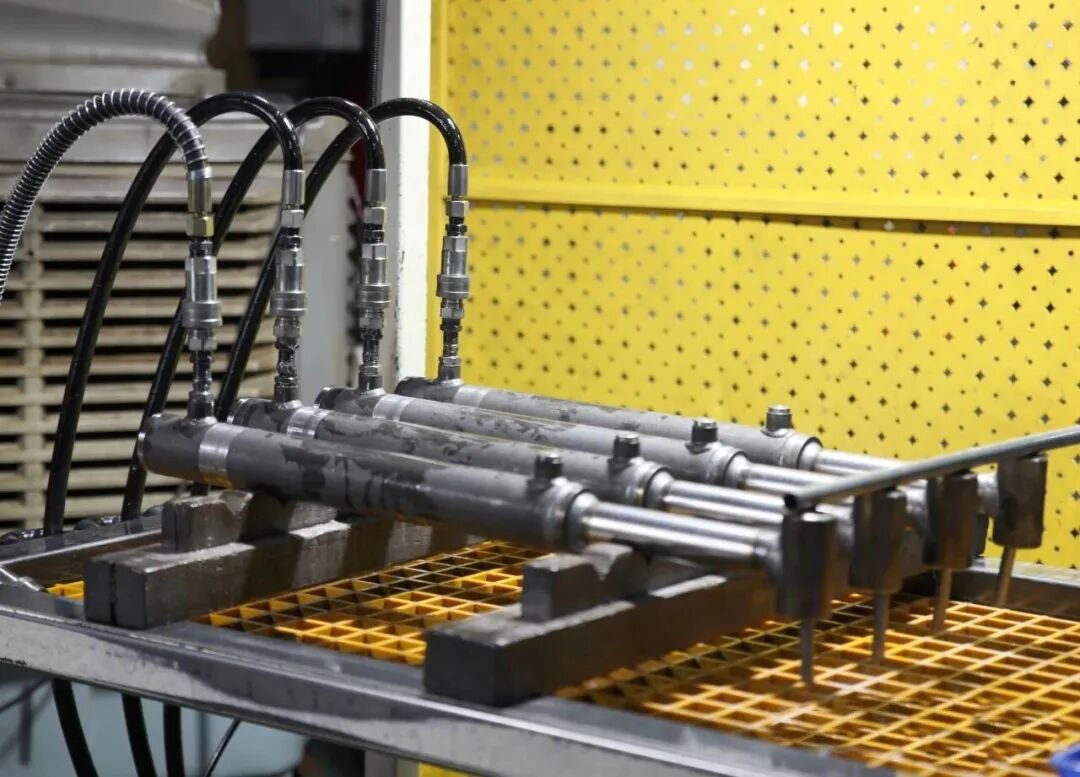
1. What a Hydraulic Cylinder Test Bench Must Control
A temporary pump connection can move a cylinder and raise a pressure gauge reading. Neither observation, on its own, constitutes a valid factory inspection. A test bench suitable for the product must establish the following conditions:
| Capability | What it must achieve |
|---|---|
| Controlled pressure | Raise pressure smoothly, stabilize it, limit maximum pressure and depressurize under control, following the approved procedure and avoiding transient overshoot. |
| Suitable flow and speed | Provide the flow required by the test. Too little flow prolongs cycling; excessive flow may cause end-of-stroke impact or conceal low-speed irregularities. |
| Directional control and isolation | Supply the relevant working chambers separately and, when required, reliably isolate the cylinder from the pressure source, return line or measurement branches. |
| Effective measurement | Use suitable measuring points, ranges, resolution and recording methods for pressure, time, stroke, temperature and leakage. |
| Secure fixtures | Restrain the cylinder, pins, fittings and end connections so that side loads, looseness or misalignment do not distort the results. |
| Fluid and cleanliness control | Control the test fluid, filtration, temperature and air removal, all of which affect sealing, friction, movement and pressure stability. |
| Safety and traceability | Include pressure limiting, guards, emergency stop, depressurization, hazardous-area exclusion, product identification and result recording in the test process. |
Published descriptions of hydraulic cylinder production test benches commonly combine no-load operation, stroke measurement, leakage and proof pressure testing. A long feature list is less important than clearly defined, repeatable conditions that another person can review.
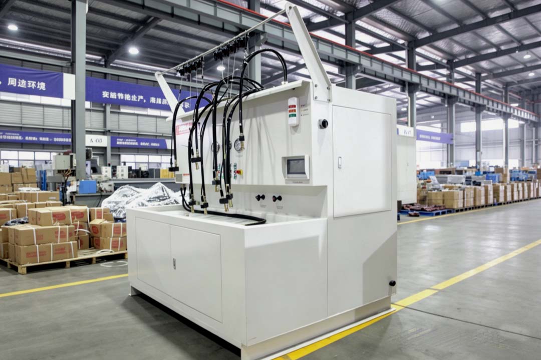
Workshop footage shows cylinder handling at a test station. The images alone do not establish the applied pressure, test sequence or acceptance result.
2. Factory Acceptance Does Not Prove Service Life
Factory inspection concerns a particular cylinder after manufacture. It asks whether that unit has passed the required acceptance and function tests under the specified conditions and criteria.
Development and design qualification address different questions through endurance, pressure impulse, limit and application testing:
- A proof pressure test is not a burst test in which pressure is increased until failure.
- One successful pressure hold does not establish fatigue life after hundreds of thousands of cycles.
- Smooth no-load travel over the full stroke cannot replace validation under side load, impact, low temperature or a particular mounting orientation.
- Passing the three basic inspection groups does not demonstrate freedom from failure in every machine and operating condition.
A manufacturer’s telescopic cylinder manual treats function, proof pressure and internal bypass as separate tests, and gives assembly drawing requirements priority when specifying pressures. The lesson is practical: each test answers a different question, and numerical requirements must come from the corresponding product documents, not from another cylinder type or an old webpage.
3. Stroke and Function Testing: More Than Measuring Rod Extension
Before formal assessment, the approved procedure normally calls for filling, bleeding and trial cycling at low pressure under low-risk conditions. Trapped air can cause springy movement, stick-slip and pressure fluctuations, while increasing stored-energy risk during subsequent high-pressure testing.
Measure Stroke Between Defined References
Measure stroke between the specified retracted and extended end positions using defined mechanical references. Exposed piston rod length, cylinder mounting distance and effective stroke are different quantities. Matching numbers are not comparable unless the reference points also match.
Stroke tolerance must come from the drawing, technical agreement, applicable product standard or approved inspection specification. There is no single tolerance that an article can assign to every cylinder.
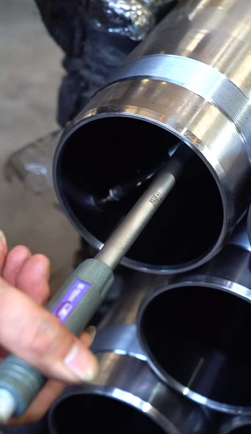
Cylinder tube bore inspection is a dimensional check. Actual assembled stroke still requires its own defined measurement references.
Verify Travel in Both Directions
For a double-acting cylinder, confirm correct extension and retraction, travel to the specified end positions, and correct installation and operation of ports and cushioning or throttling adjustment components. Telescopic cylinders may also require checks on the extension and retraction sequence of individual stages, using criteria specific to that design.
Assess Smooth, Continuous Movement
At the specified pressure, flow and mounting conditions, look for abnormal binding, stick-slip, vibration, noise, impact or end-position behavior. Manufacturer test procedures include full-stroke cycling and abnormal movement in functional assessment.
A short stroke may indicate incorrect component dimensions, an internal stop, an assembly position error or an unsuitable measurement reference. A cylinder with the correct stroke but uneven movement may instead have trapped air, seal friction, guide problems, poor coaxial alignment, contamination or unsuitable test flow. Length and motion quality require separate judgments.
Safety: Secure the cylinder before trial cycling and clear personnel and objects from the piston rod axis and the entire movement envelope. Never steady an unsecured cylinder by hand or adjust fixtures while it is moving.
4. Proof Pressure Testing: Verify the Pressure Boundary
A proof pressure test subjects the specified working chamber to a defined pressure for a defined time at a defined piston position. It checks the pressure boundary formed by the tube, end caps, welds, threads or other joints, seals and associated parts for external leakage, damage or permanent abnormal change.
Obtain Test Pressure From the Applicable Documents
Do not apply a universal pressure multiplier merely because the test is called a proof pressure test. The definitions and relationships of rated pressure, nominal pressure, maximum working pressure and test pressure must follow the current applicable standards, drawings, contract and approved procedure.
Special materials or fluids, single-acting cylinders, telescopic cylinders and cylinders with integrated valves may require different provisions.
Define the Chambers and Piston Position
A typical double-acting cylinder has two pressurized working chambers. The procedure must identify the chamber being pressurized, the connection or isolation arrangement for the opposite chamber, the piston position, and whether each chamber must be tested separately. The same indicated pressure can otherwise represent very different loading conditions.
Control Pressure Rise, Stabilization, Hold and Release
The bench must prevent pressure peaks and overshoot, record pressure at the actual measuring point and the holding time, and release stored energy under control afterward.
A slow mechanical gauge may miss a short pressure spike. A sensor positioned too far from the cylinder may also fail to represent the actual pressure at its port.
Inspect More Than the Gauge
During the test, inspect the specified locations for external leakage, abnormal deformation, loose connections and other damage. Pressure changes can originate in the cylinder, the bench circuit, temperature changes or trapped air. A pressure trace cannot replace inspection of the complete pressure boundary.
Passing confirms that the cylinder met the pressure integrity requirements under that particular set of test conditions. It does not establish burst pressure or long-term fatigue life, and the test pressure must not be treated as the permissible pressure for normal operation.
Safety: Before high-pressure testing, verify that the bench, hoses, fittings, valves, sensors, plugs, fixtures and guards are rated for the test conditions. Keep people away from the piston rod axis and possible hose-whip or fluid-jet paths. Never tighten, dismantle or check for leaks by touch while the system is pressurized.
5. Leakage Testing: Identify Which Boundary the Oil Crosses
External Leakage: Oil Reaches the Environment
Potential external leak paths include the rod seal, end caps and static seals, welds, ports, threaded connections and adjustment points. Oil drops at the rod seal or seepage elsewhere must be assessed against the applicable criteria.
Clean the cylinder and test connections before visual inspection. Residual assembly oil, oil spilled during bleeding and leaking bench fittings can otherwise be mistaken for cylinder leakage. Where measurement is required, the approved method must define the collection point, duration and units. General fluid-leak detection guidance likewise distinguishes visual inspection from pressure-change methods.
Internal Leakage: Oil Crosses an Internal Sealing Boundary
A typical internal leak passes from the pressurized chamber across the piston seal into the opposite chamber. There may be no oil on the floor, yet bypass can affect pressure holding, positioning, speed and output force.
One direct approach is to pressurize the defined chamber and correctly isolate the opposite chamber from the test circuit or connect it to a measurement branch. Flow or volume discharged from the opposite port is then measured at the specified pressure, piston position, temperature and duration. Manufacturer procedures include examples of this one-side-pressurized, opposite-port-flow method.
Two qualifications are essential:
- Allowable leakage depends on the sealing design. The same manufacturer’s manual applies different criteria to piston ring constructions and soft seals. Neither “every cylinder must have absolutely zero internal leakage” nor “every cylinder may leak the same amount” is a reliable rule.
- The bench must not contribute leakage attributed to the cylinder. Valve clearances, isolation valves, fittings, hoses and measurement branches can introduce background leakage. Verify it using a validated circuit, blank test or reference method.
Why Pressure Decay Alone Does Not Identify Piston Seal Leakage
Pressure decay testing isolates a system after pressurization and observes pressure change over a defined period. It can provide a leakage indication, but that indication is not unique to piston seal bypass.
The reading may also change because of:
- Internal or external leakage in bench valves, fittings and hoses.
- Continued compression or dissolution of air trapped in the cylinder and lines.
- Changes in oil, cylinder or ambient temperature.
- Elastic deformation and stabilization of hoses, the cylinder tube and seals under pressure.
- Measuring point location, instrument range, resolution and sampling rate.
- Changes in effective volume caused by piston movement or slight fixture movement.
Conversely, a temporarily steady reading does not automatically prove that leakage is below the product limit. An oversized instrument range, short observation time or inadequate resolution may hide a small leak.
Interpret pressure decay together with the test boundaries, stabilization time, temperature, circuit background leakage, instrument capability and acceptance limits. NIST’s explanation of metrological traceability emphasizes a documented calibration chain linking results to a reference, with uncertainty considered at each step. Saying that an instrument “has been calibrated” does not by itself show that the resulting measurement is fit for the intended purpose.
6. Combine the Tests to Build Basic Release Evidence
Stroke and function, proof pressure, and leakage provide different evidence. None duplicates the others.
| Test outcome | Supported conclusion | Remaining issue |
|---|---|---|
| Correct stroke; proof pressure test fails | Dimensions and movement may be normal. | External leakage, damage or another pressure-boundary abnormality prevents release. |
| Proof pressure test passes; internal leakage exceeds the limit | The structure may have withstood the specified pressure. | Piston seal isolation does not meet the acceptance criteria. |
| Leakage test passes; stroke is too short | Sealing boundaries may satisfy the requirements. | Component dimensions, stops or assembly positions may still be wrong. |
| All three test groups pass | Basic release evidence has been obtained under the specified conditions. | Endurance, contamination, side-load, temperature and installed-application validation remain separate requirements. |
“It reached a certain pressure, did not burst and showed no visible oil leak” is therefore insufficient to describe a complete factory inspection. It leaves stroke, internal isolation and result traceability unresolved.
A defensible acceptance decision identifies the governing documents, conditions and methods, then shows that the measured results fall within the required acceptance limits.
7. What a Useful Factory Inspection Record Contains
A report stating only “pressure test passed” offers little support for review, traceability or supplier quality discussions. Subject to the quality system and applicable documents, record at least:
- Product model, drawing number, serial or batch number, and test date.
- Applicable standards, drawings, contract, work instructions and their revisions.
- Test fluid, oil temperature and specified environmental conditions.
- Stroke measurement references, measured stroke, movement observations and acceptance criteria.
- Proof pressure chamber, piston position, pressure measuring point, actual pressure, holding time and result.
- Internal and external leakage methods, measuring locations, durations, units, measured results and limits.
- Identification and valid status of the bench and pressure, temperature, stroke and flow instruments.
- Abnormalities, repairs, retests and nonconforming-product segregation.
- Operator, reviewer and final release status.
These details let a reviewer answer three practical questions: Which cylinder was tested? Under what conditions? Why was it accepted?
Safety: High-pressure fluid can cause serious injury. Never locate or stop a suspected leak with your hands. Before disconnecting lines, releasing fixtures or moving the cylinder, confirm controlled depressurization, isolation of stored energy and a safe condition in accordance with the procedure.
Key Takeaways for Hydraulic Cylinder Factory Inspection
- The test bench must provide controlled, measurable, isolatable, recorded and safeguarded test conditions. A pump and gauge alone are insufficient.
- Stroke and function, proof pressure, external leakage and internal leakage examine different boundaries and cannot replace one another.
- Proof pressure testing verifies pressure integrity under defined conditions; it establishes neither burst pressure nor endurance life.
- Pressure decay is an indirect signal from the entire test system. Circuit leakage, temperature, trapped air, elastic deformation and instrument capability must be considered before attributing it to piston seal leakage.
- Test pressure, holding time, leakage limits, stroke tolerances and sequence must follow current applicable standards, drawings, contracts and approved procedures. Complete records make acceptance decisions reviewable.
Which Test Data Matter Most to You?
When reviewing a hydraulic cylinder factory inspection report, which actual data would you most like to see: the pressure-time curve, internal leakage rate, measured stroke or complete test conditions? Leave a comment or contact us to discuss your inspection requirements.
For more information about our hydraulic cylinder manufacturing, projects and services, please contact the Elephant Machinery team.
Contact our team