

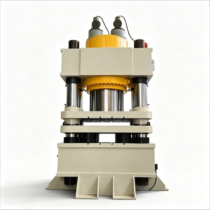
Whether you are building a 10-ton, 20-ton, 30-ton, or 50-ton benchtop or vertical shop hydraulic press, selecting the right hydraulic press cylinder is the single most critical decision in your build. Choosing the wrong bore size, mounting style, or port thread can lead to insufficient pressing force, buckled piston rods, oil leaks, or structural failure.
This guide walks you through the core hydraulic principles, exact engineering formulas, mounting mechanics, and a ready-to-use hydraulic cylinder RFQ specification sheet so you can source standard or custom cylinders directly from a manufacturer with confidence.
1. Core Hydraulic Cylinder Terminology You Must Know
Think of a hydraulic cylinder as a heavy-duty steel syringe:
- The hydraulic pump pushes pressurized hydraulic oil into the cylinder barrel.
- The hydraulic cylinder converts fluid pressure into linear mechanical force—producing a downward pushing force (thrust) and an upward retraction force (pull).
Before sizing your cylinder or contacting a hydraulic cylinder manufacturer, master these 6 essential terms:
| Term | Symbol | Plain-English Meaning | What It Determines |
|---|---|---|---|
| Bore Diameter | The inner diameter of the cylinder barrel (not the outer diameter!) | Determines the maximum tonnage (pushing force) of your press | |
| Rod Diameter | The diameter of the polished chrome piston rod that extends outward | Determines buckling resistance under load and retraction pull force | |
| Stroke | The maximum travel distance from fully retracted to fully extended | Determines how far the press ram can move up and down | |
| Working Pressure | Hydraulic oil pressure, typically measured in MPa | Pressure × Area = Force. Common workshop builds use 16 MPa or 21 MPa | |
| Closed Height (Mounting Distance) | Total length from the mounting surface to the rod end when fully retracted | Determines how tall your press frame must be welded | |
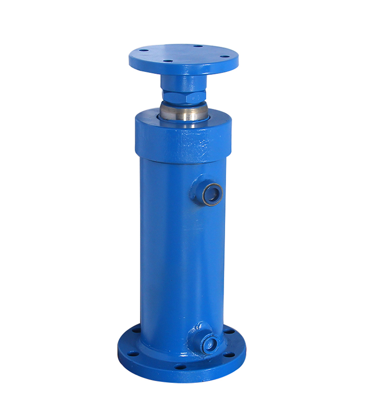
| Oil Ports | The two threaded ports for high-pressure hoses (cap-end feed / rod-end return) | Determines the hydraulic hose fittings you need to purchase |
Tip
Common Beginner Mistake: Bore Diameter Is Not Outer Diameter!
When measuring an existing cylinder or requesting a quote from a factory, terms like “100 cylinder” or “125 cylinder” always refer to the inner bore diameter (), never the outer wall diameter of the barrel.
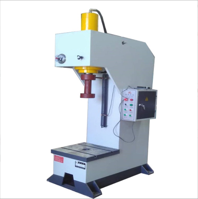
2. Step 1: Calculate Required Force (System Pressure & Bore Sizing)
Before choosing what a cylinder looks like, you must answer two foundational questions:
- How many tons of force do you need? (Bearing and bushing pressing typically requires 10–20 tons; sheet metal stamping, bending, and hot forging typically require 20–50 tons.)
- What system pressure will your hydraulic power unit run?
1. How to Choose System Working Pressure ()
Higher pressure allows a smaller, more compact cylinder for the same tonnage, but it dramatically increases the demands on the pump, hoses, seals, and frame welds:
- 16 MPa (approx. 160 kg/cm²) — Best for DIY & General Workshop Builds: The most mature, forgiving pressure tier. Pumps, directional valves, and seal kits are widely available and affordable, with lower leak risk, less noise, and lower heat generation.
- 21 MPa (approx. 210 kg/cm²) — Recommended for Compact/Advanced Builds: Standard medium-high pressure (typical for tie-rod cylinders and piston/gear pumps), delivering the same tonnage in a more compact cylinder footprint.
- 25 – 31.5 MPa — Not Recommended for Beginners: High-pressure industrial territory requiring expensive axial piston pumps and high-pressure seamless steel tubing. Even a slightly loose fitting can spray high-pressure oil, posing serious safety hazards.
2. The Golden Calculation Formulas
Keep this simple rule of thumb in mind: 1 MPa of pressure exerts 10 kg (0.01 metric tons) of force per square centimeter.
Thrust (Force) Formula:
Required Bore Diameter () Formula:
Practical Example: Building a 20-Ton Hydraulic Press at 16 MPa
- Plug values into the formula:
- Round to a National Standard Bore Size:
- Cylinder bores are not arbitrary; always select from the standard metric bore series:
40, 50, 63, 80, 100, 125, 140, 160, 180, 200 (mm). - The closest standard bore to 126.2 mm is 125 mm (delivering ~19.6 tons at 16 MPa, which is sufficient for most 20-ton tasks). If you want extra headroom, step up to 140 mm or adjust the relief valve to 16.5 MPa to hit a full 20 tons.
- Cylinder bores are not arbitrary; always select from the standard metric bore series:
Important
Why You Must Stick to Standard Bore Sizes
Ordering a non-standard bore (such as 130 mm) forces the factory to custom-machine a barrel instead of using stocked honed tubing—doubling the cost, extending lead times, and making replacement seals nearly impossible to find later.
3. Quick-Reference Tonnage & Bore Chart
| Target Max Thrust | Recommended Bore @ 16 MPa | Recommended Bore @ 21 MPa | Actual Thrust @ 16 MPa |
|---|---|---|---|
| 10 Tons | 90 mm or 100 mm | 80 mm | 100 mm bore ≈ 12.5 tons |
| 20 Tons | 125 mm | 110 mm or 125 mm | 125 mm bore ≈ 19.6 tons |
| 30 Tons | 160 mm (≈ 32 tons) | 140 mm (≈ 32 tons) | 160 mm bore ≈ 32.1 tons |
| 50 Tons | 200 mm | 180 mm | 200 mm bore ≈ 50.2 tons |
(Note: Theoretical calculations exclude ~3%–5% seal friction loss. We recommend leaving a 10% safety margin—for example, using a 125 mm bore and setting the relief valve to 17–18 MPa for a reliable 20 tons, as 16 MPa-rated cylinders are typically engineered to withstand up to 21 MPa.)
3. Step 2: Key Cylinder Dimensions & Speed Matching
Once your bore diameter () is locked in, define the rod diameter (), stroke (), and pump flow rate ().
1. Selecting the Piston Rod Diameter ()
Thicker is not always better, and too thin is dangerous:
- Too thin: The rod can bend like a chopstick under heavy compression (column buckling).
- Too thick: Increases cost and reduces the annular area on the rod side, lowering upward retraction pull force (though return speed increases).
Rule of Thumb: Choose a piston rod diameter between 0.5 and 0.7 times the bore diameter , matched to standard rod sizes:
- 80 mm bore 45 mm or 50 mm rod
- 100 mm bore 55 mm, 63 mm, or 70 mm rod
- 125 mm bore 70 mm or 80 mm rod
- 160 mm bore 90 mm, 100 mm, or 110 mm rod
2. Selecting the Stroke ()
Do not over-spec the stroke. Longer strokes increase cylinder cost, require a taller press frame, and increase the risk of rod buckling at full extension.
Calculation Formula:
For most benchtop and vertical shop presses, a 150 mm – 300 mm stroke is the most practical sweet spot. If your workpieces vary widely in height (e.g., 5 cm bearings vs. 40 cm weldments), build an adjustable pin-hole worktable rather than buying an oversized 500 mm stroke cylinder.
3. Don’t Build a “Snail Press” (Flow Rate & Pressing Speed)
A common mistake is powering a large-bore cylinder with a tiny pump, resulting in a ram that crawls at 2 mm/s. The larger the bore, the more oil volume is required per millimeter of travel.
Pressing Speed Formula:
Real-World Comparison (125 mm Bore Cylinder):
- With a 4 L/min small pump (~1.5 kW motor):
— completing a 200 mm stroke takes ~37 seconds. - With a 10 L/min pump (~3 kW motor or hi-lo dual-stage pump):
— completing a 200 mm stroke takes ~15 seconds, which feels responsive and comfortable.
Tip
The Fast & Budget-Friendly Secret: If your shop only has single-phase 220V power (limiting motor size to 2.2–3 kW), use a hi-lo dual-stage hydraulic pump. It delivers high flow at low pressure for rapid approach, then automatically shifts to low flow at high pressure when the ram contacts the workpiece—giving you both speed and full tonnage.
4. Step 3: Cylinder Mounting Styles & Load Mechanics
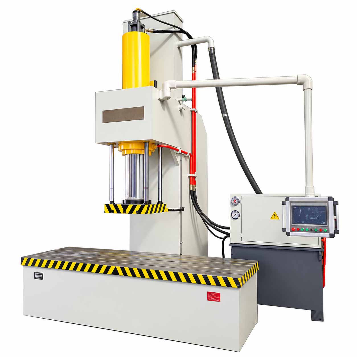
Most vertical hydraulic presses use an H-frame (gantry) or C-frame structure with an inverted top-mounted cylinder pressing downward. Choosing the wrong mounting method can shear mounting bolts or cause catastrophic cylinder failure.
Common Hydraulic Cylinder Mounting Comparison
| Mounting Code | Name | Structural Feature | Suitability for Vertical Presses |
|---|---|---|---|
| FA | Front Flange (rod-end square/round flange) | Flange is located at the rod-extension end | ⭐⭐⭐⭐⭐ Top Choice (Best for vertical presses) |
| FB | Rear Flange (cap-end flange) | Flange is located at the rear/bottom cap | ⭐⭐⭐ Usable, but puts high stress on bolts if unsupported |
| TC / MT4 | Intermediate Trunnion | Two cylindrical pins protrude from the barrel midpoint | ⭐⭐ Only for pivoting/oscillating mechanisms |
| LA / LB | Foot Mount | Base brackets like feet on the floor | ⭐⭐ Best for horizontal presses; awkward for vertical frames |
| CA / CB | Single / Double Clevis | Pin hole at the rear cap end | ⭐ Ideal for excavator arms; rarely used on presses |
Why Front Flange (FA) Is the Gold Standard for Vertical Presses
Compare the load path of these two mounting configurations:
[Recommended Mount A: Front Flange (FA) seated on or through the top beam]
┌─────────┐
│ Barrel │ <-- Cylinder barrel passes through or sits above the top beam
──┴─────────┴── <-- Front flange rests directly on the I-beam / steel plate
═══════════════ <-- Upper crossbeam (steel plate bears 100% of thrust; bolts only locate!)
│
▼ (Pressing down pushes the flange tighter against the beam—bolts never shear!)
[Risky Mount B: Rear Flange (FB) hanging underneath the top beam]
═══════════════ <-- Upper crossbeam
──┬──┬───┬──┬── <-- Entire cylinder hangs from 4 bolts
│ │Barrel │ │
└──┴─────┴──┘
▼ (At 20 tons, upward reaction force puts bolts under extreme shear/tension if unbacked!)Key Rule: If you must mount a Rear Flange (FB) cylinder underneath a crossbeam, ensure the rear cylinder cap sits flush and tightly braced against the steel crossbeam plate so the structural steel absorbs the 20-ton reaction force, leaving the bolts solely to hold the cylinder in place.
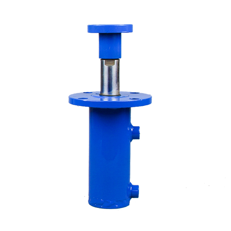
Rod-End Connections & Anti-Eccentric Loading
- Rod End: Specify an external male thread (e.g.,
M36×2orM42×2) or a welded/bolted circular press flange plate so you can easily swap dies and press heads. - Anti-Eccentric Loading Rule: Hydraulic cylinders are designed strictly for axial pushing and pulling—never side loads (bending forces). Pressing off-center or uneven workpieces forces the rod against the gland, chewing up seals within days and potentially bending the piston rod.
- Solution: For precision stamping or die pressing, install external guide columns and bushings on both sides of the cylinder so the guide rods absorb all lateral forces.
5. Step 4: Off-the-Shelf Standard vs. Custom Factory Cylinders
- Off-the-Shelf Standard Cylinders (Fastest & Most Economical):
- HOB / MOB Tie-Rod Cylinders (square end caps held by four long tie rods): The ultimate choice for DIY presses. They offer standardized FA/FB flange mounts, operate cleanly at 14–21 MPa, and allow you to replace seals yourself by simply unbolting four nuts—no special spanner wrenches required.
- HSG Welded Engineering Cylinders (round welded barrels common on agricultural/construction equipment): Rugged and budget-friendly, though they typically default to clevis mounts and require factory modification for flange mounting.
- Custom Factory Cylinders:
- When you need a specific stroke, custom bolt-circle flange dimensions, or an ultra-compact closed height, order directly from a hydraulic cylinder manufacturer. As long as you use standard metric bore and rod sizes, custom machining adds minimal cost and typically ships within days.
6. Step 5: Copy-and-Paste Hydraulic Cylinder RFQ Specification Sheet
Never ask a supplier, “How much for a 20-ton press cylinder?”—they cannot quote accurately without specifications. Send the completed Hydraulic Cylinder RFQ & Customization Sheet below to get an exact quote immediately:
RFQ Template (Copy & Customize)
[Hydraulic Cylinder RFQ / Custom Order Specification]
1. Quantity: 1 pc
2. Cylinder Type: Tie-Rod Cylinder (HOB) / Welded Engineering Cylinder (HSG) / Custom (Choose one)
3. Rated Working Pressure: 16 MPa (or 21 MPa — please match barrel wall thickness and seals)
4. Bore Diameter (ID, D): 125 mm
5. Piston Rod Diameter (d): 70 mm (or 80 mm)
6. Effective Stroke (S): 250 mm
7. Mounting Style: Front Flange (FA) / Rear Flange (FB) (Please provide flange OD, bolt circle, and hole size drawing for confirmation)
8. Rod End Configuration: External male thread (e.g., M42×2, length 45 mm, with lock nut) / Plain rod with welded flange plate
9. Oil Port Specification & Orientation:
- Thread Size: G1/2 (or M22×1.5 — parallel metric/BSPP threads preferred for bonded seal washers)
- Port Orientation: Both cap-end and rod-end ports aligned on the same side (0° orientation)
10. Working Medium & Environment: Standard #46 anti-wear hydraulic oil, ambient workshop temperature
11. Quality & Testing Requirements:
- Piston rod must be quenched & tempered and hard-chrome plated;
- Factory pressure test at 1.25–1.5× rated pressure prior to shipment (zero external or internal leakage);
- Air bleeders / cushioning: Optional (generally not required for low-speed presses; specify if needed).Include a Simple 5-Dimension Hand Sketch
If the factory requests dimensional confirmation, sketch a quick drawing marking these 5 critical dimensions:
Port B (Return) Port A (Extend)
│ │
┌──────┴──────────────────────────────┴──┐
│ │ ───
│ [ Bore ID: D ] │ ▲
────┤ │ Flange Dimensions
(Rod│ ═══[ Rod Dia: d ]═════════════════════│ (W × H, Bolt Circle, Hole Dia)
────┤ │ ▼
│ │ ───
└────────────────────────────────────────┘
│◄────── Closed Height (Retracted L_min) ►│
│◄─ Stick-out ─►│
(Male Thread Spec)7. Step 6: Vetting Your Cylinder Manufacturer & Receiving Inspection
1. 4 Must-Ask Technical Questions for the Factory
- “What materials and processes are used for the barrel and piston rod?”
- Standard: The barrel must be #20 or #45 cold-drawn seamless honed tubing (mirror-smooth ID); the piston rod must be #45 steel, quenched & tempered, with hard-chrome plating for wear and corrosion resistance.
- “What brand of seals do you install?”
- Standard: Avoid ultra-cheap generic rubber rings that leak within six months. Choose NOK (Japan) or Hallite (UK) for top-tier durability, or Taiwan DZ (Dingzing) polyurethane seals for strong cost-performance.
- “What are the port threads, and do they use flat-face sealing?”
- Pro Tip: Specify G threads (BSPP, e.g., G1/2, G3/8) or Metric parallel threads (e.g., M22×1.5, M18×1.5) with flat port bosses so you can seal effortlessly using bonded washers or O-rings. Avoid tapered pipe threads (NPT/ZG), which beginners easily cross-thread or over-tighten to the point of cracking the port boss.
- “Do you perform factory pressure testing, and what is the warranty?”
- Standard: Reputable factories test every cylinder at 1.25–1.5× rated pressure for several minutes to verify zero leakage, and offer a 6-month to 1-year warranty (covering manufacturing defects, excluding rod scoring or side-load damage).
2. 4-Point Receiving Inspection Checklist
When your hydraulic cylinder arrives, inspect these 4 items immediately before installation:
- Inspect the Piston Rod Surface: The hard-chrome finish must be mirror-bright with zero dents, scratches, or pinholes. Even a grain-of-sand pit will shred the rod seal like a file during operation.
- Check Port Protection & Cleanliness: Verify that plastic dust plugs are installed in both ports. Check inside for metal shavings or weld slag—if any debris is present, flush thoroughly with clean hydraulic oil or kerosene before plumbing, or it will destroy your pump and valves.
- Verify Key Dimensions: Use calipers or a tape measure to confirm the rod-end thread, flange bolt-hole spacing, and port orientation match your frame drawing.
- Inspect Welds (for Welded Cylinders): Welds should be uniform and continuous, free of porosity or slag inclusions.
8. Final Safety Red Lines (Mandatory Pre-Test Checklist)
Stored hydraulic energy is unforgiving—an uncontrolled 20-ton force carries the destructive energy of a small explosive. Before powering up your press:
- Always Install a Pressure Relief Valve (Safety Valve)!
Your pump outlet or directional control valve must include a relief valve set to your target working pressure (e.g., 16 MPa). Without it, once the cylinder bottoms out, the pump will spike pressure past 30–40 MPa until a hose bursts, the cylinder ruptures, or the motor burns out. - Never Use Plumbing Pipe Fittings or Galvanized Hardware!
Every line must use wire-braided high-pressure hydraulic hose (such as 1SN / 2SN, rated for 25 MPa+) paired with carbon-steel hydraulic fittings. Cast-iron, brass, or galvanized water pipe fittings from a hardware store will violently burst. - Design Your Frame for at Least 2× the Cylinder Thrust
When a cylinder pushes down with 20 tons, the crossbeams and columns experience 20 tons of tensile and bending stress. Weld your press frame with a minimum safety factor of 2× (engineered for 40+ tons on a 20-ton press). During initial testing, never stand directly in front of the cylinder or fittings—bleed all air at zero load first, then step up pressure gradually.
For more information about our hydraulic cylinder manufacturing, projects and services, please contact the Elephant Machinery team.
Contact our team